Yaskawa G5HHP Drive User Manual
Page 184
Advanced Operation
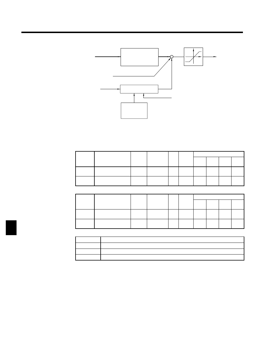
7.3.3 Torque Control
7 - 20
Torque reference
Torque reference
primary delay filter
(d5-02)
+
+
+
Torque limit
(L7-01 to L7-04)
Torque compensation bias
Speed limit
Speed limiting circuit
Speed limit
bias (d5-05)
Speed feedback
Internal torque
reference
Fig 7.9
Torque Control Block Diagram
J
Torque Reference Settings: H3-04, H3-05, H3-08, H3-09
D
Set the multi-function analog input terminal 42 (H3-05) or 39 (H3-09) to torque reference (a setting of
13). The torque reference value cannot be set with the Digital Operator.
User
Change
during
Setting
Factory
Valid Access Levels
User
Constant
Number
Name
g
during
Opera-
tion
Setting
Range
Unit Factory
Setting
V/f
Control
V/f with
PG
Open
Loop
Vector
Flux
Vector
H3-05
Multi-function analog
input (terminal 42)
x
0 to 1F
--
0
B
B
B
B
H3-09
Multi-function analog
input (terminal 39)
x
1 to 1F
--
1F
A
A
A
A
D
Next, set the signal level for the analog input terminal that was set to torque reference.
User
Change
during
Setting
Factory
Valid Access Levels
User
Constant
Number
Name
g
during
Opera-
tion
Setting
Range
Unit Factory
Setting
V/f
Control
V/f with
PG
Open
Loop
Vector
Flux
Vector
H3-04
Signal level selection
(terminal 42)
x
0, 1
--
0
B
B
B
B
H3-08
Signal level selection
(terminal 39)
x
0 to 2
--
2
A
A
A
A
D
Signal Level Settings
Setting
Function
0
0 to +10 V input (When H3-08 is being set, be sure to disconnect jumper wire J1.)
1
0 to ±10 V input (When H3-08 is being set, be sure to disconnect jumper wire J1.)
2
4 to 20 mA input (H3-08 only)
D
Set the proper signal level for the torque reference that you want to input.
D
The direction of the torque that is output is determined by the sign (polarity) of the signal that was input.
It is not determined by the direction of the run command (forward/reverse).
•
+Voltage (or current):
Forward torque reference (generally counterclockwise; axis side)
•
--Voltage:
Reverse torque reference (generally clockwise; axis side)
Since the polarity of the voltage input determines the direction, only forward torque references can be
input when the “0 to +10 V” or “4 to 20 mA” signal level has been selected. If you want to input reverse
torque references, be sure to select the “0 to ±10 V” signal level.
7