Yaskawa G5HHP Drive User Manual
Page 84
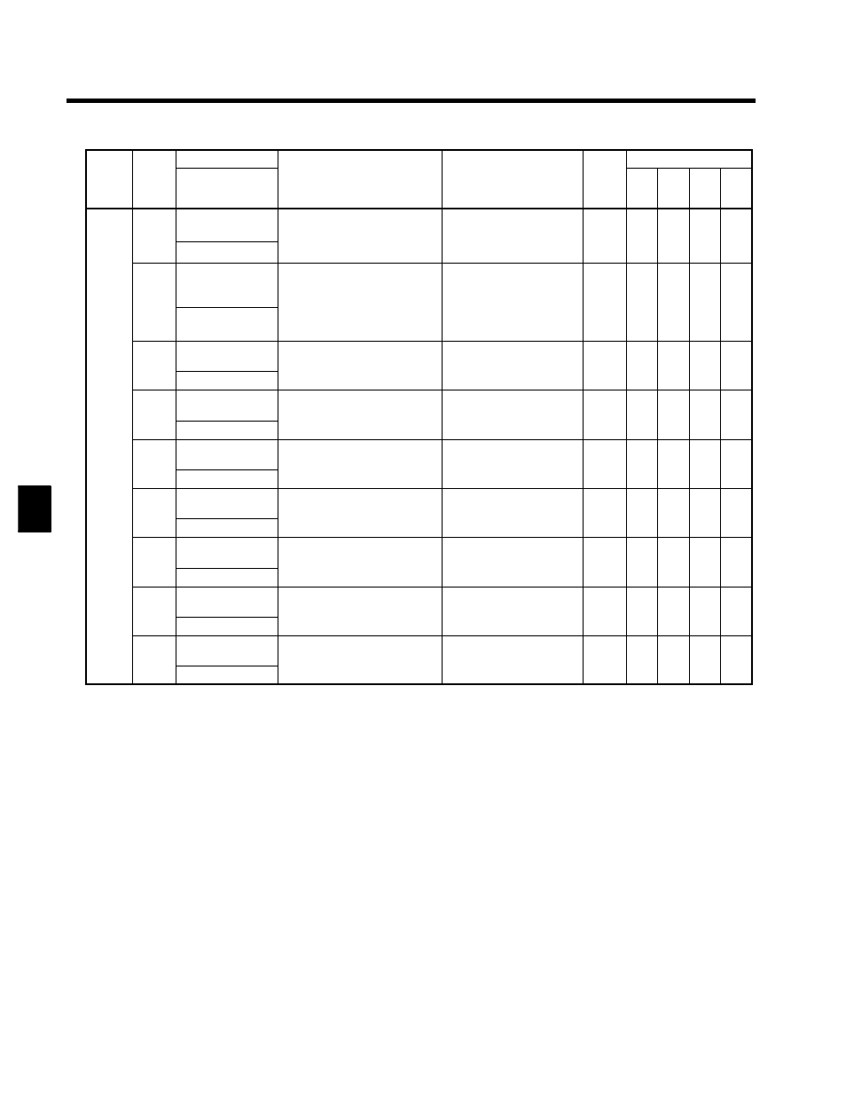
Setting User Constants
4.2.4 Operation Mode
4 - 16
Func-
tion
Valid Access Levels
Min.
Unit
Output Signal Levels for
Multi-function Analog
Outputs
Function
Name
Con-
stant
No.
Func-
tion
Flux
Vec-
tor
Open
-loop
Vec-
tor
V/f w/
PG
V/f
Min.
Unit
Output Signal Levels for
Multi-function Analog
Outputs
Function
Digital Operator
Display
Con-
stant
No.
U1-24
PID feedback val-
ue
Monitors the feedback value when
PID control is used.
Th inp t for th m
fr q nc
10 V: Max. frequency
(0 to ±10 V possible)
0.01 %
A
A
A
A
U1 24
PID Feedback
The input for the max. frequency
corresponds to 100%.
(0 to ±10 V possible)
0.01 %
A
A
A
A
U1-25
DI-16H2 input sta-
tus
Monitors the reference value from
a VS-616G5-DI16H2 Digital Ref-
erence Card.
The value will be displayed in
Can’t be output.
--
A
A
A
A
U1 25
DI-16 Reference
The value will be displayed in
binary or BCD depending on user
constant F3-01.
Can t be output.
--
A
A
A
A
U1-26
Output voltage ref-
erence (Vq)
Monitors the Inverter’s internal
voltage reference value for the
10 V: 400 (575) VAC
(0 to ±10 V possible)
0.1 V
X
X
A
A
U1 26
Voltage Ref (Vq)
voltage reference value for the
motor’s secondary current control. (0 to ±10 V possible)
0.1 V
X
X
A
A
U1-27
Output voltage ref-
erence (Vd)
Monitors the Inverter’s internal
voltage reference value for the
10 V: 400 (575) VAC
(0 to ±10 V possible)
0.1 V
X
X
A
A
Status
U1 27
Voltage Ref (Vd)
voltage reference value for the
motor’s excitation current control. (0 to ±10 V possible)
0.1 V
X
X
A
A
Status
Moni-
tor
U1-28
Software No.
(CPU)
Manufacturer’s CPU software ID
number
Can’t be output.
0.1 V
A
A
A
A
U1 28
CPU ID
number
Can t be output.
0.1 V
A
A
A
A
U1-32
ACR output of q
axis
Monitors current control output
value for motor’s secondary cur-
10 V: 100%
0.1 %
X
X
A
A
U1 32
ACR (q) Output
value for motor s secondary cur
rent.
10 V: 100%
0.1 %
X
X
A
A
U1-33
ACR output of d
axis
Monitors current control output
value for motor’s excitation cur-
10 V: 100%
0.1 %
X
X
A
A
U1 33
ACR (d) Output
value for motor s excitation cur
rent.
10 V: 100%
0.1 %
X
X
A
A
U1-34
OPE fault
constant
Shows the first constant number
where an OPE fault is detected
Can’t be output.
--
A
A
A
A
U1 34
OPE Detected
where an OPE fault is detected.
Can t be output.
--
A
A
A
A
U1-35
Zero servo move-
ment pulses
Shows the number of PG pulses
for the movement range at the
Can’t be output.
1
X
X
X
A
U1 35
Zero Servo Pulse
for the movement range at the
stop point for a zero servo times 4.
Can t be output.
1
X
X
X
A
4