5 function block diagram, Appendix – Yaskawa G5HHP Drive User Manual
Page 356
Appendix
12 - 8
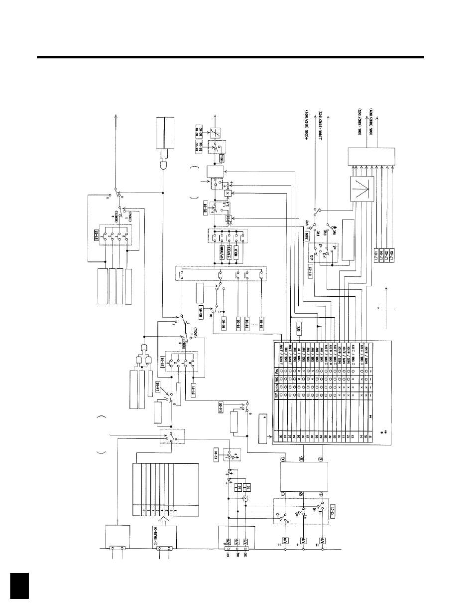
12.5 Function Block Diagram
RUN
co
m
m
an
d
O
pt
ional
C
ar
d
pr
ov
ided
at
th
e
C
connec
to
r
M
ult
i-f
unc
tion
input
(O
pt
ion
selec
ted)
1000/
1
H
z
re
fe
renc
e:
Fr
equenc
y
Fr
ef
Ju
m
p
fr
equenc
y
pr
oc
es
si
-
in
g
W
hen
th
e
fr
equenc
y
re
fe
renc
e
is
set
to
D
I-
01
to
D
I-
08,
fr
equenc
y
gai
n
and
fr
equenc
y
bi
as
ar
e
inv
al
id
.
(s
ee
not
e
2)
(s
ee
not
e
2)
Tr
ans
m
is
si
on
opt
ion
ot
her
than
S
I-
K
2
S
I-
K
2
opt
ion
C
ont
ro
lc
irc
uit
te
rm
inal
(T
er
m
inals
1
and
2)
B
inar
y
D
igit
al
O
per
at
or
M
ul
ti-
func
tion
input
M
ul
ti-
st
ep
speed
re
fe
renc
e
(s
ee
not
e
2)
(s
ee
not
e
2)
M
ult
i-f
unc
tion
input
(=
C
)
C
los
ed
or
not
se
le
ct
ed
O
pen
M
ult
i-f
unc
tion
input
(01)
(Loc
al/
rem
ot
e
selec
tion)
S
et
the
m
ult
i-f
unc
tion
input
to
01.
LO
C
A
L
(O
per
at
or
)
W
hen
fr
equenc
y
re
fe
re
nc
e
is
di
sa
bl
ed
S
I-
K
2
opt
ion
dependi
ng
on
th
e
ty
pe
of
W
hen
fr
equenc
y
re
fe
re
nc
e
is
di
sabl
ed
A
ut
om
at
ica
lly
se
le
ct
ed
O
pt
ic
al
C
ar
d
to
be
m
ount
ed.
B
C
D
1%
unit
C
-c
onnec
to
r
F
req
u
en
cy
ref
er
en
ce
F3-
01
D
I-
08:
255/
100%
(O
pt
ion)
se
ttin
g
se
tt
ing
m
ode
(O
pt
ion)
B
C
D
5-
di
gi
ti
nput
/0
.0
1
H
z
uni
t
B
C
D
0.
1%
unit
B
C
D
0.
01%
unit
B
C
D
1
H
z
unit
B
C
D
0.
1
H
z
unit
B
C
D
0.
01
H
z
unit
D
I-
18H
(12-
bit
selec
ted)
:
4095/
100%
D
I-
18H
(16-
bit
selec
ted)
:
30000/
100%
S
peed
cont
ro
l
Tr
ans
m
is
si
on
opt
io
n
ot
her
than
To
rque
re
fe
renc
e:
Tr
ef
To
rque
co
m
pens
at
ion:
Tc
om
p
To
rque
cont
ro
l
S
I-
K
2
(T
or
que
re
fe
renc
e,
To
rque
co
m
pens
at
ion)
Re
fe
r
to
th
e
H
3-
06
(T
er
m
inal
16)
H
3-
09
(T
er
m
inal
14)
A
I-
14B
13
bi
ts
(O
pt
ion)
9b
its
9b
its
9b
its
(s
ee
not
e
1)
R
egener
at
ion
for
to
rque
lim
it
A
ID
et
ailed
B
loc
k
D
iagr
am
.
S
ettin
g
Funct
ion
Input
level
A
ux
iliar
y
frequenc
y
ref
er
enc
e
Fr
equenc
y
gai
n
Vo
ltage
bi
as
Fr
equenc
y
bias
(r
ot
at
ion
dir
ec
tion
unc
hanged)
A
cc
el/
Dec
el
change
(r
educ
tion
coef
fic
ient
)
D
C
injec
tion
br
ak
ing
cu
rr
ent
O
ver
to
rque
det
ec
tion
lev
el
S
tall
pr
ev
ent
ion
lev
el
dur
ing
run
Fr
equenc
y
ref
er
enc
e
lower
lim
it
lev
el
Ju
m
p
fr
equenc
y
P
ID
feedbac
k
P
ID
tar
get
va
lu
e
Fr
equenc
y
bi
as
For
w
ar
d
si
de
tor
que
lim
it
R
ev
er
se
sid
e
to
rq
ue
lim
it
Fo
rw
ar
d/
re
ve
rs
e
tor
que
lim
it
No
tu
se
d
To
rque
re
fe
renc
e
fo
rt
or
que
cont
ro
l
To
rque
lim
it
fo
rs
peed
cont
ro
l
To
rque
co
m
pens
at
ion
H
3-
09
cannot
be
se
tt
o
“00”
.
N
ot
e
1:
W
hen
A
I-
14B
is
not
m
ount
ed,
oper
at
ion
w
ill
be
th
e
sam
e
as
w
hen
R
ef
er
to
the
A
ID
et
ailed
B
loc
k
D
iagr
aam
on
th
e
nex
tpage.
F
2-
01
is
set
to
1
regar
dles
s
of
the
F
2-
01
set
tings
.
2:
P
os
si
ble
to
change
only
w
hile
th
e
m
ot
or
is
st
opped.
3:
W
hen
changing
to
th
e
volt
age
input
,s
et
th
e
H
3-
08
to
0
or
1
and
cu
tt
he
jum
per
cable
(J
1)
on
the
C
ont
ro
lC
ar
d.
For
w
ar
d
tor
que
lim
it
R
ev
er
se
tor
que
lim
it
1s
tquadr
ant
Mi
ni
mu
m
pr
ior
ity
2nd
quadr
ant
3r
d
quadr
ant
4t
h
quadr
ant
To
rque
S
peed
2nd
quadr
ant
1s
tquadr
ant
3r
d
quadr
ant
4t
h
quadr
ant
Tr
ans
m
is
si
on
opt
ion
ot
her
than
S
I-K
2
O
n
th
e
nex
tpage.
C
-c
onnec
to
r
C
-c
onnec
to
r
Terminal 36
Terminal 42
12