Yaskawa G5HHP Drive User Manual
Page 207
7.5 Common Functions
7 - 43
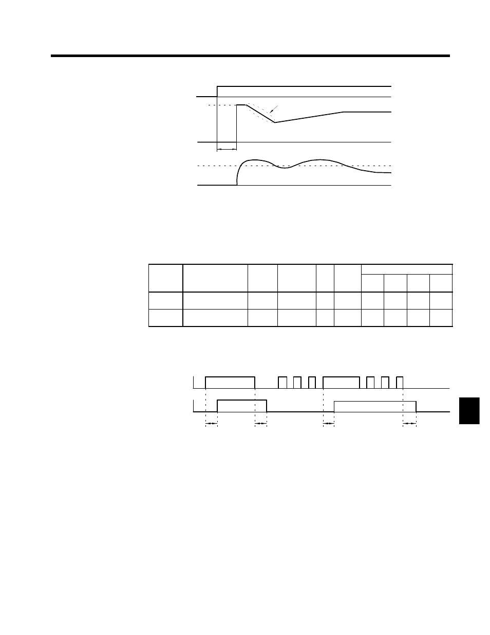
Run command
OFF
ON
Maximum output
frequency
Deceleration time set for b3-03
Frequency
reference
that is set
Output frequency
Minimum baseblock time (L2-03)
b3-02
Output current
Fig 7.19
Speed Search Timing Chart
J
Timer Functions: b4-01, b4-02
D
The timer functions are enabled when the timer function input (setting: 18) and the timer function output
(setting: 12) are set for the multi-function input and multi-function output respectively.
D
These inputs and outputs serve as general-purpose I/O. Chattering of sensors, switches, and so on, can
be prevented by setting a delay time.
User
Change
during
Setting
Factory
Valid Access Levels
User
Constant
Number
Name
g
during
Opera-
tion
Setting
Range
Unit Factory
Setting
V/f
Control
V/f with
PG
Open
Loop
Vector
Flux
Vector
b4-01
Timer function ON-
delay time
x
0.0 to 300.0
s
0.0
A
A
A
A
b4-02
Timer function OFF-
delay time
x
0.0 to 300.0
s
0.0
A
A
A
A
D
When the timer function input ON time is longer than the value set for b4-01 (timer function ON-delay
time), the timer function output turns ON.
D
When the timer function input OFF time is longer than the value set for b4-02 (timer function OFF-delay
time), the timer function output turns OFF. An operation example of the timer function is shown in Fig-
ure 7.20.
Timer function
input
Timer function
output
b4-01
b4-02
b4-01
b4-02
ON
ON
ON
ON
Fig 7.20
Operation Example of Timer Function
J
PID Control Settings: b5-01 to b5-08
The PID control function is a control system that matches a feedback value (i.e., a detected value) to the set
target value. Combining proportional (P), integral (I), and derivative (D) control makes control possible
even for a mechanical system with dead time.
This section explains the PID control applications and operations, along with the constant settings and tun-
ing procedure.
PID Control Applications
Table 7.6 shows examples of PID control applications using the Inverter.
7