Yaskawa G5HHP Drive User Manual
Page 313
9.1 Protective and Diagnostic Functions
9 - 3
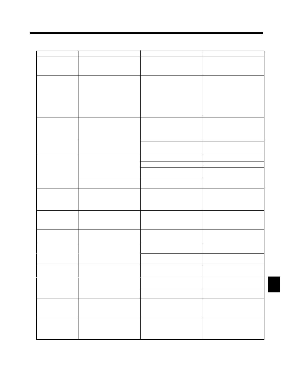
Corrective Actions
Probable Causes
Meaning
Fault Display
UV3
MC Answerback
Inrush Prevention Circuit Fault
A fault occurred in the inrush preven-
tion circuit.
----
S
Try turning the power supply off and
on.
S
Replace the Inverter if the fault con-
tinues to occur.
PF
Input Pha Loss
Main Circuit Voltage Fault
The main circuit DC voltage oscillates
unusually (not when regenerating).
This fault is detected when L8-05 is
set to “Enabled.”
S
An open-phase occurred in the input
power supply.
S
A momentary power loss occurred.
S
The wiring terminals for the input
power supply are loose.
S
The voltage fluctuations in the input
power supply are too large.
S
The voltage balance between phases
is bad.
Reset the fault after correcting its
cause.
LF
Output Pha Loss
Output Open-phase
An open-phase occurred at the Invert-
er output.
This fault is detected when L8-07 is
set to “Enabled.”
S
There is a broken wire in the output
cable.
S
There is a broken wire in the motor
winding.
S
The output terminals are loose.
Reset the fault after correcting its
cause.
Output Pha Loss
The motor being used has a capacity
less than 5% of the Inverter’s maxi-
mum motor capacity.
Check the motor and Inverter capacity.
Cooling Fin Overheating
The ambient temperature is too high.
Install a cooling unit.
OH OH1
H
i k O
The temperature of the Inverter’s
cooling fins exceeded the setting in
There is a heat source nearby.
Remove the heat source.
Heatsink Over tmp
cooling fins exceeded the setting in
L8-02 or 105°C.
The Inverter’s cooling fan has
stopped.
Replace the cooling fan. (Contact your
Inverter internal cooling fan
stopped
Inverter internal cooling fan has
stopped.
Replace the cooling fan. (Contact your
Yaskawa representative.)
RH
Dyn Brk Resistor
Installed Braking Resistor Over-
heating
The braking resistor is overheated and
the protection function set with L8-01
has operated.
The deceleration time is too short and
the regenerative energy from the mo-
tor is too large.
S
Reduce the load, increase the decel-
eration time, or reduce the motor
speed.
S
Change to a Braking Resistor Unit.
RR
Dyn Brk Transistr
Internal Braking Transistor Fault
The braking transistor is not operating
properly.
----
S
Try turning the power supply off and
on.
S
Replace the Inverter if the fault con-
tinues to occur.
OL1
Motor Overload
The motor overload protection func-
tion has operated based on the internal
l
i h
l
l
The load is too heavy. The accelera-
tion time, deceleration time, and cycle
time are too short.
Check the size of the load and the
length of the acceleration, decelera-
tion, and cycle times.
OL1
Motor Overloaded
tion has operated based on the internal
electronic thermal value.
The V/f characteristics voltage is too
high.
Check the V/f characteristics.
The motor’s rated current setting
(E2-01) is incorrect.
Check the motor’s rated current set-
ting (E2-01).
OL2
Inverter Overload
The Inverter overload protection func-
tion has operated based on the internal
l
i h
l
l
The load is too heavy. The accelera-
tion time, deceleration time and cycle
time are too short.
Check the size of the load and the
length of the acceleration, decelera-
tion, and cycle times.
OL2
Inv Overloaded
tion has operated based on the internal
electronic thermal value.
The V/f characteristics voltage is too
high.
Check the V/f characteristics.
The Inverter capacity is too low.
Replace the Inverter with one that has
a larger capacity.
OL3
Overtorque Det 1
Overtorque 1
There has been a current greater than
the setting in L6-02 for longer than
the setting in L6-03.
----
S
Make sure that the settings in L6-02
and L6-03 are appropriate.
S
Check the mechanical system and
correct the cause of the overtorque.
OL4
Overtorque det 2
Overtorque 2
There has been a current greater than
the setting in L6-05 for longer than
the setting in L6-06.
----
S
Make sure that the current setting in
L6-05 and time setting in L6-06 are
appropriate.
S
Check the mechanical system and
correct the cause of the overtorque.
9