Yaskawa G5HHP Drive User Manual
Page 131
6.1 Common Settings
6 - 13
DC injection braking time
b2-04 x 10
b2-04
Output frequency
when the stop
command is input
10 %
100% (Max. frequency)
Run command
ON
OFF
Min. baseblock time
(L2-03)
DC injection braking time
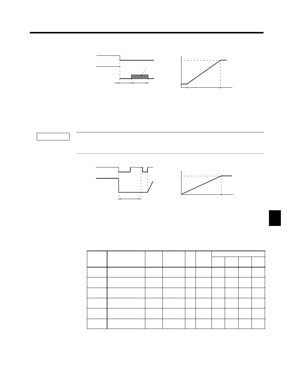
DC injection braking
After the stop command is input and the minimum baseblock time (L2-03) has elapsed, DC
injection braking is applied and the motor stopped.
The DC injection braking time depends upon the output frequency when the stop command is
input and the “DC injection braking time at stop” setting in b2-04, as shown in Figure 6.6.
Output frequency
Fig 6.6
DC Injection Braking Stop
Lengthen the minimum baseblock time (L2-03) when an overcurrent (OC) occurs during stopping. When the
power to an induction motor is turned OFF, the counter-electromotive force generated by the residual magnetic
field in the motor can cause an overcurrent to be detected when DC injection braking is applied.
•
Coast to Stop with Timer (b1-03 = 3)
Time T
0
Deceleration
time
Output frequency
when the stop
command is input
100% (Max. frequency)
Run command
ON
OFF
Output frequency
ON
ON
T
0
After the stop command is input, run commands are disregarded until the time T
0
has
elapsed. The time T
0
depends upon the output frequency when the stop command is
input and the deceleration time.
Fig 6.7
Coast to Stop with Timer
6.1.8 Multi-function Input Settings: H1-01 through H1-06
D
Set the functions for terminals 11 to 16. Set the functions of the multi-function inputs according to the
application.
User
Change
during
Setting
Factory
Valid Access Levels
User
Constant
Number
Name
g
during
Opera-
tion
Setting
Range
Unit Factory
Setting
V/f
Control
V/f with
PG
Open
Loop
Vector
Flux
Vector
H1-01
Multi-function input 1
(terminal 11)
x
0 to 77
--
24
B
B
B
B
H1-02
Multi-function input 2
(terminal 12)
x
0 to 77
--
14
B
B
B
B
H1-03
Multi-function input 3
(terminal 13)
x
0 to 77
--
3 (0)
B
B
B
B
H1-04
Multi-function input 4
(terminal 14)
x
0 to 77
--
4 (3)
B
B
B
B
H1-05
Multi-function input 5
(terminal 15)
x
0 to 77
--
6 (4)
B
B
B
B
H1-06
Multi-function input 6
(terminal 16)
x
0 to 77
--
8 (6)
B
B
B
B
D
The default settings in parentheses are the default values when the Unit is initialized for 3-wire sequence
control.
6
IMPORTANT