Yaskawa G5HHP Drive User Manual
Page 246
Advanced Operation
7.5.5 External Terminal Functions: H
7 - 82
S
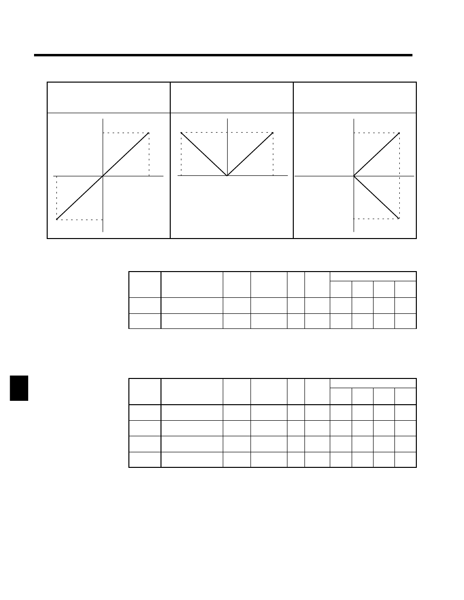
Torque Reference (Setting: 13)
S
Torque Compensation Bias (Setting: 14)
S
Forward Torque Limit (Setting: 10)
S
Reverse Torque Limit (Setting: 11)
S
Regenerative Torque Limit (Setting: 12)
S
Forward/Reverse Torque (Speed) Limit (Set-
ting: 15)
--10 V
0
10 V
100 %
--100 %
--10 V
0
10 V
100 %
0
10 V
100 %
--100 %
J
Multi-function Analog Output Settings: H4-01 to H4-07
Function Selection Constants: H4-01, H4-04
User
Change
during
Setting
Factory
Valid Access Levels
User
Constant
Number
Name
g
during
Opera-
tion
Setting
Range
Unit Factory
Setting
V/f
Control
V/f with
PG
Open
Loop
Vector
Flux
Vector
H4-01
Monitor selection (ter-
minal 45)
x
1 to 35
--
2
B
B
B
B
H4-04
Monitor selection (ter-
minal 48)
x
1 to 35
--
3
B
B
B
B
D
The multi-function outputs can be set to monitor any of the U1 Inverter status items by setting the last
two digits of the constant number (U1-jj).
Refer to page 4 - 14 for a table listing all of these U1 settings.
D
Settings 4, 10, 11, 12, 13, 14, 25, 28 and 34 can’t be set and settings 29, 30, and 31 aren’t used.
Adjusting the Monitor Output: H4-02, -03, -05, -06
User
Change
during
Setting
Factory
Valid Access Levels
User
Constant
Number
Name
g
during
Opera-
tion
Setting
Range
Unit Factory
Setting
V/f
Control
V/f with
PG
Open
Loop
Vector
Flux
Vector
H4-02
Gain (terminal 45)
f
0.00 to 2.50 Mul-
tiple
1.00
B
B
B
B
H4-03
Bias (terminal 45)
f
--10.0 to
+10.0
%
0.0
B
B
B
B
H4-05
Gain (terminal 48)
f
0.00 to 2.50 Mul-
tiple
0.50
B
B
B
B
H4-06
Bias (terminal 48)
f
--10.0 to
+10.0
%
0.0
B
B
B
B
D
For the output gain, set what multiple of 10 V will correspond to a 100% output of the monitored item.
D
For the output bias, set the amount that the output characteristic will be shifted vertically.
Set this amount as a percentage, with 10 V corresponding to 100%.
7