5 wiring control circuit terminals, 1 control circuit terminal functions – Yaskawa G5HHP Drive User Manual
Page 52
Wiring
3.5.1 Control Circuit Terminal Functions
3 - 12
3.5 Wiring Control Circuit Terminals
3.5.1 Control Circuit Terminal Functions
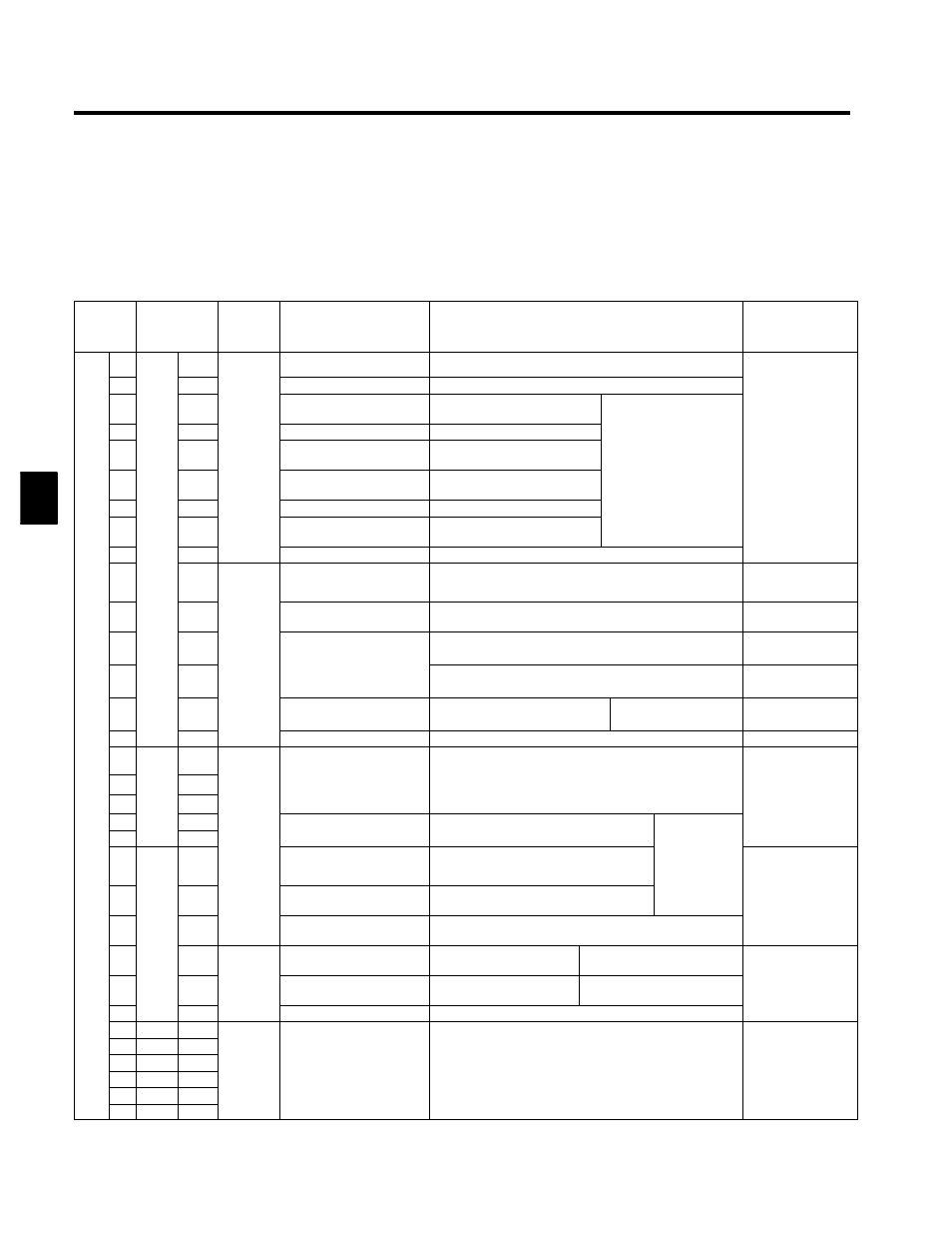
The functions of the control circuit terminals are shown in Table 3.2. Use the appropriate terminals for the
correct purposes.
Table 3.2 Control Circuit Terminals
External
Terminal
Code
Control PCB
Terminal
Code
Type
Signal Name
Function
Signal Level
1TB
9
9CN
17
Forward run/stop command Forward run when CLOSED; stopped when OPEN.
24 VDC, 8 mA
10
18
Reverse run/stop command Reverse run when CLOSED; stopped when OPEN.
,
Photocoupler isolation
11
19
External fault input
Fault when CLOSED; normal
when OPEN.
Multi-function contact in-
puts
(C
d i
l
b
Photocoupler isolation
12
20
Fault reset
Reset when CLOSED
p
(Command signals can be
selected by setting H1-01
13
21
Sequence
output
i
l
Main/auxiliary switch
Auxiliary frequency reference
when CLOSED.
selected by setting H1-01
to H1-06.)
14
22
output
signals
Multi-step speed reference
2
Multi-step setting 2 when
CLOSED.
15
23
Jog frequency reference
Jog run when CLOSED.
16
24
External baseblock
Inverter output stopped when
CLOSED.
17
25
Sequence input common
--
34
1
15 V power output
15 V power supply for analog references
15 V
(Max. current: 20 mA)
44
10
--15 V power output
--15 V power supply for analog references
--15 V
(Max. current: 20 mA)
36
4
Analog
input
Master speed frequency
reference
--10 to 10 V/--100% to 100%
0 to 10 V/0 to 100%
--10 to +10 V (20 kΩ)
0 to 10 V (20 kΩ)
39
6
input
signals
4 to 20 mA/0 to 100%
--10 to +10V/--100% to +100% 0 to 10V/0 to 100%
4 to 20 mA (250Ω)
42
8
Multi-function analog input --10 to 10 V/--100% to 100%
0 to 10 V/0 to 100%
Auxiliary analog input
(H3-05)
--10 to +10 V (20 kΩ)
0 to 10 V (20 kΩ)
35
3
Analog input common
--
52
TB2
2
Fault output signal
(Si l
l d bl h
Terminals 23 and 52 become open when output signal is
faulty
Dry contacts
Contact capacity:
25
3
(Single-pole, double-throw
contact)
faulty.
Terminals 23 and 25 become closed when output signal is
Contact capacity:
1 A max. at 250 VAC
23
1
contact)
Terminals 23 and 25 become closed when output signal is
faulty.
1 A max. at 250 VAC
1 A max. at 30 VDC
53
4
Running signal (1NO con-
t t)
Operating when CLOSED.
Multi-function
t t
57
5
Sequence
t t
g g
(
tact)
p
g
outputs
19 10CN
10
q
output
signals
Zero speed detection
Zero level (b2-01) or below when
CLOSED
Open-collector output
50 mA max. at 48 V*
20
12
Speed agree detection
Within ±2 Hz of set frequency when
CLOSED.
50 mA max. at 48 V
50
18
Open-collector output com-
mon
--
45
2
Analog
Frequency output
0 to 10 V/100% frequency
Multi-function analog monitor
1 (H4-01, H4-02)
0 to ±10 V max. ±5%
2 mA max.
48
4
Analog
output
signals
Current monitor
5 V/Inverter rated current
Multi-function analog monitor
2 (H4-04,H4-05)
2 mA max.
46
3
g
Analog output common
--
29
--
--
For shield connection
38
--
--
41
--
--
Shield strip
47
--
--
Shield strip
connection
--
--
51
--
--
58
--
--
3