Wiring – Yaskawa G5HHP Drive User Manual
Page 44
Wiring
3 - 4
IM
U/T1
FM
Analog output
monitor
Frequency meter
+
Forward run command
(forward when closed)
9
Forward Run/Stop
V/T2
T/L3
S/L2
R/L1
W/T3
+
--
Reverse run command
(reverse when closed)
10
(External fault)
11
(Fault reset)
12
(Master/auxiliary speed)
13
(Multi-step speed 2)
14
(External baseblock
reference)
15
Sequence common
(Insulated from 0 V
terminal)
38
36
Master speed frequency ref-
erence
(--10 to +10V/0 to 10V)
39
42
Speed reference
common
35
0V
MCCB
Speed setting adjust-
ment resistor (2 kΩ)
Speed setting
resistor (2 kΩ)
Fault contact output
250 VAC, 1 A max.
30 VDC, 1 A max.
Operation output
250 VAC, 1 A max.
30 VDC, 1 A max.
45
0V
48
25
52
23
57
19
20
50
1
17
Shield terminal
2TB
1TB
1TB
Frequency reference
46
Braking Unit
(Optional)
T1/L31
S1/L21
R1/L11
*Power transformer for
12-phase rectification
PG
AM
+
Output am-
meter
PG
4CN
2CN
3CN
Ventilation fan fault detection
F1
F2
+15 V power for analog
reference
--15 V power for analog refer-
ence
44
Multi-function
analog input
16
(Jog reference)
34
Frequency reference
53
200-VAC input terminals for
ventilation fan
Control power input
terminals
200/
r/
2
400/
1
575 V:
400
2
r200
200
200
575/
575
2
(Not for 575 V)
VS--616G5
Motor
Braking Resistor Unit (Optional)
(Optional)
(Optional)
(Optional)
Monitor
Open collector 1
Multi-function output common
Multi-function
open-collector output
48 VDC, 50 mA max.
Multi-function analog input
(--10 to +10 V/0 to 10 V)
Master speed frequency
reference (4 to 20 mA)
Reference
When using the 12-phase
rectification input, remove the input
terminal short-circuit bus bar.
Reverse Run/Stop
Multi-function contact
input 1
Multi-function contact
input 2
Multi-function contact
input 3
Multi-function contact
input 4
Multi-function contact
input 5
Multi-function contact
input 6
Note
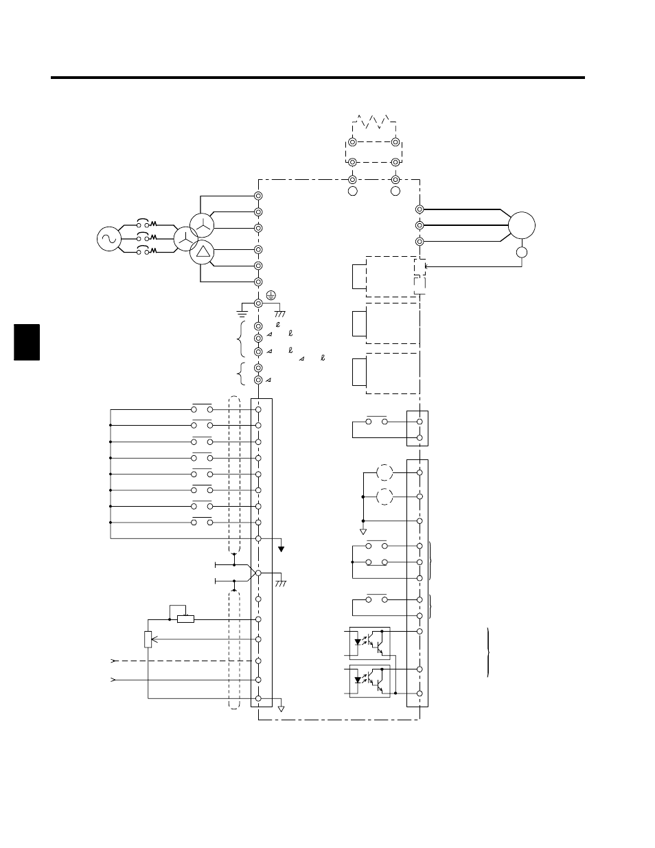
(1) Double circles indicate main circuit terminals and single circles indicate control circuit terminals.
(2) When using the 12-phase rectification, the user must prepare the transformer.
Open collector 2
2TB
Fig 3.1
Connection Diagram (Model CIMR-G5A4200 Shown Above)
3