6 terminal constants: h, Multi-function inputs: h1 – Yaskawa G5HHP Drive User Manual
Page 292
User Constants
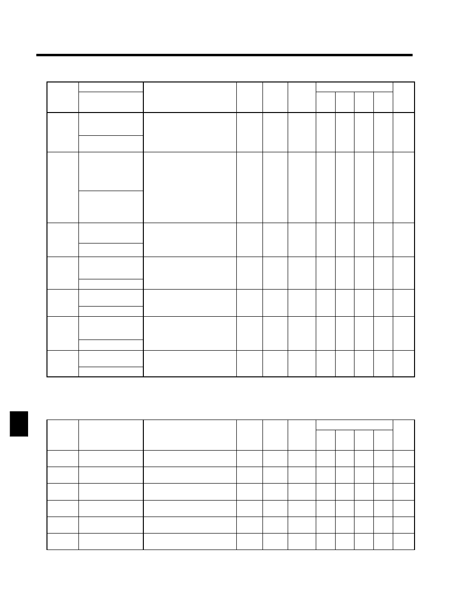
8.2.6 Terminal Constants: H
8 - 26
Constant
Number
Page
Control Methods
Change
during
Opera-
tion
Factory
Setting
Setting
Range
Description
Name
Constant
Number
Page
Flux
Vector
Open
Loop
Vector
V/f
with
PG
V/f
Change
during
Opera-
tion
Factory
Setting
Setting
Range
Description
Display
F6-01
Output mode selec-
tion
Effective when a DO-08 Digital
Output Card is used.
Set the output mode.
0, 1
0
x
B
B
B
B
7 - 60
F6 01
DO-08 Selection
Set the output mode.
0: 8-channel individual outputs
1: Binary code output
0, 1
0
x
B
B
B
B
7 - 60
F7-01
Frequency multiple
selection
Effective when the Pulse Monitor
Card is used.
Sets the number of output pulses.
0: 1F, 1: 6F, 2: 10F, 3: 12F, 4: 36F
;
F= the output frequency dis-
0 to 4
1
x
B
B
B
B
7 - 61
F7 01
PO-36F Selection
;
F= the output frequency dis-
played in Hz.
Example: When 0 (1F) is set, and
the output frequency is 60 Hz, 60
pulses per second are output.
(50% duty)
0 to 4
1
x
B
B
B
B
7 - 61
F8-01
Optical option (SI-
F/G)
0: Deceleration to stop
1: Coast to stop
2 Em r nc stop
0 to 3
1
f
B
B
B
B
----
F8 01
E-15 Det Sel
2: Emergency stop
3: Continue operation
0 to 3
1
f
B
B
B
B
----
F9-01
External fault input
level from Optical op-
tion
0: NO contact
1: NC contact
0, 1
0
x
B
B
B
B
----
E-15 Selection
1: NC contact
F9-02
External fault from
Optical option
0: Always detect
1: Detect during operation
0, 1
0
x
B
B
B
B
----
F9 02
EFO Detection
1: Detect during operation
0, 1
0
x
B
B
B
B
----
F9-03
Action for external
fault from Optical op-
tion
0: Deceleration to stop
1: Coast to stop
2: Emergency stop
0 to 3
1
x
B
B
B
B
----
EFO Fault Act
2: Emergency stop
3: Continue operation
F9-04
Optical option trace
sampling time
----
0 to
60000
0
x
B
B
B
B
----
F9 04
Trace Sample Time
----
60000
0
x
B
B
B
B
----
8.2.6 Terminal Constants: H
J
Multi-function Inputs: H1
C
t t
S tti
F t
Change
Control Methods
Constant
Number
Name
Display
Setting
Range
Factory
Setting
Change
during
Opera-
tion
V/f
V/f
with
PG
Open
Loop
Vector
Flux
Vector
Page
H1-01
Multi-function input 1
(terminal 11)
Terminal 11 Sel
0 to 77
24
x
B
B
B
B
7 - 63
H1-02
Multi-function input 2
(terminal 12)
Terminal 12 Sel
0 to 77
14
x
B
B
B
B
7 - 63
H1-03
Multi-function input 3
(terminal 13)
Terminal 13 Sel
0 to 77
3 (0) *
x
B
B
B
B
7 - 63
H1-04
Multi-function input 4
(terminal 14)
Terminal 14 Sel
0 to 77
4 (3) *
x
B
B
B
B
7 - 63
H1-05
Multi-function input 5
(terminal 15)
Terminal 15 Sel
0 to 77
6 (4) *
x
B
B
B
B
7 - 63
H1-06
Multi-function input 6
(terminal 16)
Terminal 16 Sel
0 to 77
8 (6) *
x
B
B
B
B
7 - 63
8