3 setting/adjusting motor constants – Yaskawa G5HHP Drive User Manual
Page 170
Advanced Operation
7.1.3 Setting/Adjusting Motor Constants
7 - 6
D
Fine-tune the gain when motor operation is unstable causing hunting to occur or torque/speed respon-
siveness is low.
•
When hunting occurs, increase the gain by 0.05 increments while checking the motor responsive-
ness.
•
When responsiveness is low, decrease the gain by 0.05 increments while checking the motor respon-
siveness.
7.1.3 Setting/Adjusting Motor Constants
J
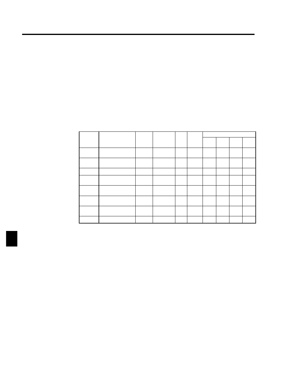
Adjusting the V/f Pattern: E1-04 through E1-10, E1-13
Normally it isn’t necessary to adjust the V/f pattern with open-loop vector control. Adjust the V/f pattern
when you want to change the maximum output frequency setting or decrease the Inverter’s output voltage
or when stalls are occurring during no-load operation.
To increase the motor’s rated speed, increase the maximum output frequency in E1-04 in programming
mode after autotuning.
It is possible to make user-defined V/f pattern settings (E1-04 through E1-10) in open-loop vector control
mode. (The preset V/f patterns cannot be selected.)
User
Change
during
Setting
Factory
Valid Access Levels
User
Constant
Number
Name
g
during
Opera-
tion
Setting
Range
Unit Factory
Setting
V/f
Control
V/f with
PG
Open
Loop
Vector
Flux
Vector
E1-04
Max. output frequen-
cy
x
50.0 to
150.0
Hz
60.0
Q
Q
Q
Q
E1-05
Max. voltage
x
0.0 to 510.0
*1
VAC 400.0
*1
Q
Q
Q
Q
E1-06
Base frequency
x
0.0 to 150.0
Hz
150.0
Q
Q
Q
Q
E1-07
Mid. output frequen-
cy
x
0.0 to 150.0
Hz
3.0
*2
Q
Q
A
x
E1-08
Mid. output frequen-
cy voltage
x
0.0 to 510.0
*1
VAC
22.0
*1, *2
Q
Q
A
x
E1-09
Min. output frequen-
cy
x
0.0 to 150.0
Hz
0.5
Q
Q
Q
A
E1-10
Min. output frequen-
cy voltage
x
0.0 to 510.0
*1
VAC
4.0
*1, *2
Q
Q
A
x
E1-13
Base voltage
x
0.0 to 510.0 VAC
0.0
A
A
Q
Q
* 1. These voltages are for 400-V Class Inverters; multiply the voltage by approx. 1.5 for 575-V
Class Inverters.
* 2. The default setting depends on the Inverter’s capacity. The default settings shown in the table
are for 400-V Class, 200 to 800 kW Inverters. (See page 8 - 42.)
Note 1.The default settings for E1-07 through E1-10 depend on the control method. The default
settings shown in the table are for open-loop vector control. (See page 8 - 41.)
2. The four frequency settings must satisfy the following formula:
E1-04 (F
MAX
) ≥ E1-06 (F
A
) > E1-07 (F
B
) ≥ E1-09 (F
MIN
)
3. When making the V/f characteristics a straight line, set the same value in E1-07 (middle
output frequency) and E1-09 (minimum output frequency). In this case, constant E1-08
(middle output frequency voltage) will be disregarded.
4. If E1-13 is set to 0.0, the same value as in E1-13 will be set for E1-05. It does not normally
need to be set separately.
7