Yaskawa G5HHP Drive User Manual
Page 260
Advanced Operation
7.5.6 Protective Functions: L
7 - 96
D
L6-01/L6-04 Settings
Setting
Function
Display
0
Overtorque detection disabled
Overtorque detection 1
Overtorque output 2
1
Detect only during speed agree. Continue
operation even after detection. (Minor fault) “OL3” blinks
“OL4” blinks
2
Detect overtorque at any time. Continue op-
eration even after detection. (Minor fault)
“OL3” blinks
“OL4” blinks
3
Detect only during speed agree. Stop output
after detection. (Fault
)
“OL3” lights
“OL4” lights
4
Detect overtorque at any time. Stop output
after detection. (Fault)
“OL3” lights
“OL4” lights
D
When overtorque detection is enabled, be sure to set the overtorque detection level (L6-02 or L6-05)
and the overtorque detection time (L6-02 or L6-05). An overtorque condition is detected when the cur-
rent exceeds the overtorque detection level for longer than the overtorque detection time.
D
The overtorque detection level settings depend on the control method:
•
Open-loop or flux vector control: Set as a percentage of the motor rated torque.
•
Normal V/f or V/f with PG feedback control: Set as a percentage of the Inverter rated current.
D
Any of the following functions can be set in a multi-function output (H2-01, H2-02, or H2-03) to indi-
cate fact that an overtorque condition has been detected.
S
Setting B: Overtorque detection 1 (NO)
S
Setting 18: Overtorque detection 2 (NO)
S
Setting 17: Overtorque detection 1 (NC)
S
Setting 19: Overtorque detection 2 (NC)
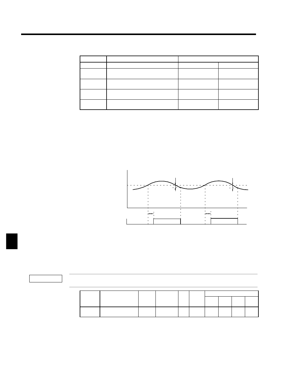
Motor current
(Output torque)
L6-02 or L6-05
Overtorque Detection 1 (N.O.)
or Overtorque Detection 2
(N.O.)
ON
L6-03
or
L6-06
*
*
ON
L6-03
or
L6-06
* The overtorque detection is cleared when the current drops about 5% of the
Inverter’s rated current (or the motor’s rated torque).
Fig 7.47
Timing Chart for Overtorque Detection
J
Hardware Protection Settings: L8-01 to L8-03, L8-05, L8-07
Protection Selection for Internal DB Resistor: L8-01
Always set to 0 when using a Large-capacity Slim Type Inverter.
User
Change
during
Setting
Factory
Valid Access Levels
User
Constant
Number
Name
g
during
Opera-
tion
Setting
Range
Unit Factory
Setting
V/f
Control
V/f with
PG
Open
Loop
Vector
Flux
Vector
L8-01
Protect selection for
internal DB resistor
x
0, 1
--
0
B
B
B
B
D
Settings
7
IMPORTANT