7 user constants, Appendix – Yaskawa G5HHP Drive User Manual
Page 360
Appendix
12 - 12
12.7 User Constants
Factory settings are given for a 400-V class Inverter of 200 kW set to open loop vector control (A1-02 = 2).
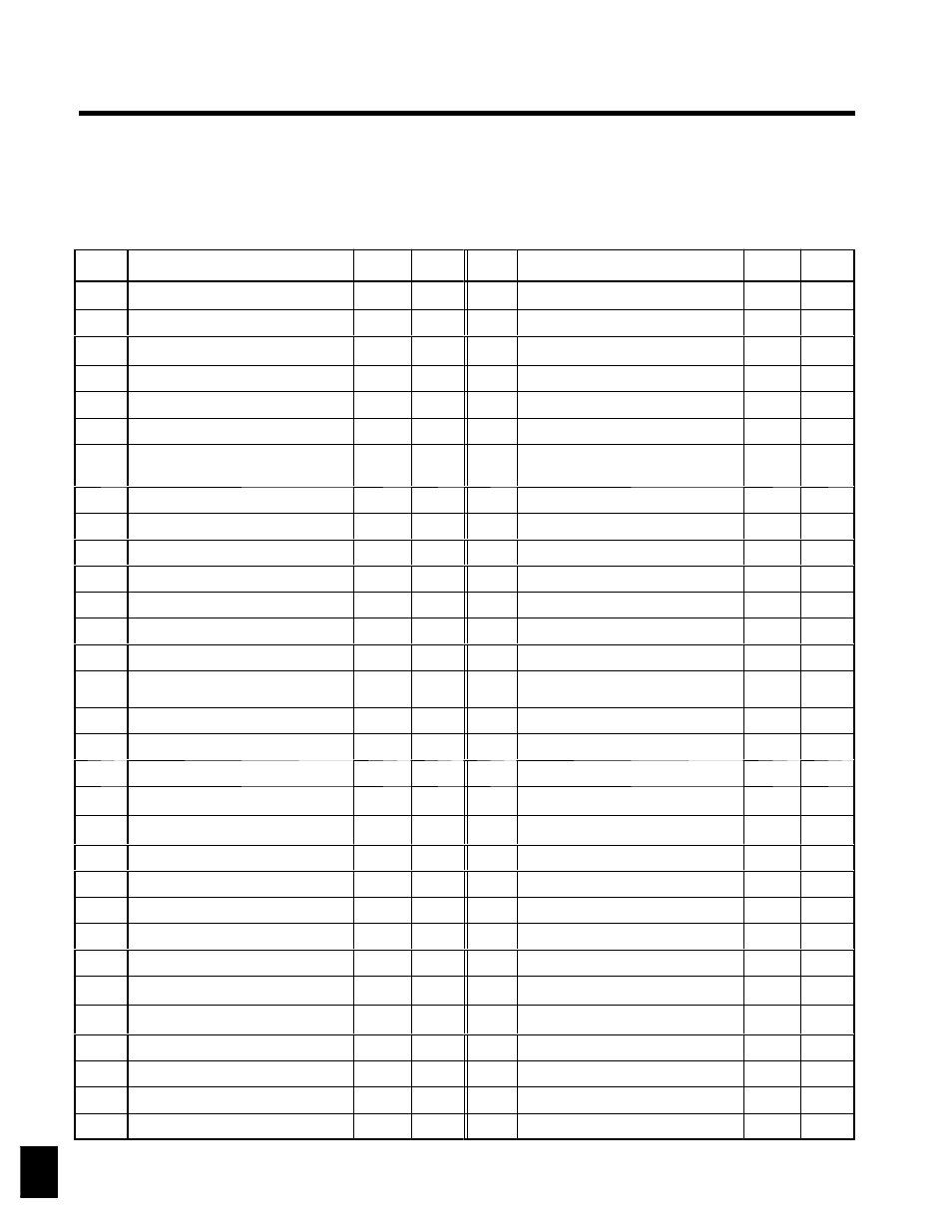
Table 12.1 User Constants
No.
Name
(Display)
Factory
Setting
Setting
No.
Name
(Display)
Factory
Setting
Setting
A1-00
Language selection for digital operator display
(Select Language)
1
*
1
b6-01
Dwell frequency at start
(Dwell Ref @ Start)
0.0
A1-01
Constant access level
(Access Level)
2
b6-02
Dwell time at start
(Dwell Time @ Start)
0.0
A1-02
Control method selection
(Control Method)
2
*
1
b6-03
Dwell frequency at stop
(Dwell Ref @ Stop)
0.0
A1-03
Initialize
(Init Parameters)
0
b6-04
Dwell time at stop
(Dwell Time @ Stop)
0.0
A1-04
Password 1
(Enter Password)
0
b7-01
Droop control gain
*2
(Droop Gain)
0.0
A1-05
Password 2
(Select Password)
0
b7-02
Droop control delay time
2
(Droop Delay Time)
0.05
A2-01
to
A2-32
User setting constant
(User Pram 1 to 32)
------
b8-01
Energy-saving gain
(Energy Save Gain)
80
b1-01
Reference selection
(Reference Source)
1
b8-02
Energy-saving frequency
(Energy Save Freq)
0.0
b1-02
Operation method selection
(Run Source)
1
b9-01
Zero-servo gain
(Zero Servo Gain)
5
b1-03
Stopping method selection
(Stopping Method)
0
b9-02
Zero-servo completion width
(Zero Servo Count)
10
b1-04
Prohibition of reverse operation
(Reverse Oper)
0
C1-01
Acceleration time 1
(Accel Time 1)
10.0
b1-05
Operation selection for setting of E1-09 or less
(Zero-Speed Oper)
0
C1-02
Deceleration time 1
(Decel Time 1)
10.0
b1-06
Read sequence input twice
(Cntl Input Scans)
1
C1-03
Acceleration time 2
(Accel Time 2)
10.0
b1-07
Operation after switching to remote mode
*2
(LOC/REM RUN Sel)
0
C1-04
Deceleration time 2
(Decel Time 2)
10.0
b2-01
Zero speed level (DC injection braking start fre-
quency)
(DCInj Start Rreq)
0.5
C1-05
Acceleration time 3
(Accel Time 3)
10.0
b2-02
DC injection braking current
(DCinj Current)
50
C1-06
Deceleration time 3
(Decel Time 3)
10.0
b2-03
DC injection braking time at start
(DCInj Time @ Start)
0.00
C1-07
Acceleration time 4
(Accel Time 4)
10.0
b2-04
DC injection braking time at stop
(DCInj Time @ Stop)
0.50
C1-08
Deceleration time 4
(Decel Time 4)
10.0
b3-01
Speed search selection at start
(SpdSrch at Start)
0
*
3
C1-09
Emergency stop time
(Fast Stop Time)
10.0
b3-02
Speed search operating current
(SpdSrch Current)
100
*
3
C1-10
Accel/decel time setting unit
(Acc/Dec Units)
1
b3-03
Speed search deceleration time
(SpdSrch Dec Time)
2.0
C1-11
Accel/decel time switching frequency
(Acc/Dec SW Freq)
0.0
b4-01
Timer function ON-delay time
(Delay-ON Timer)
0.0
C2-01
S-curve characteristic time at acceleration start
(SCrv Acc @ Start)
0.20
b4-02
Timer function OFF-delay time
(Delay-OFF Timer)
0.0
C2-02
S-curve characteristic time at acceleration end
(SCrv Acc @ End)
0.20
b5-01
PID control mode selection
(PID Mode)
0
C2-03
S-curve characteristic time at deceleration start
(SCrv Dec @ Srat)
0.20
b5-02
Proportional gain (P)
(PID Gain)
1.00
C2-04
S-curve characteristic time at deceleration end
(SCrv Dec @ End)
0.00
b5-03
Integral (I) time
(PID I Time)
1.0
C3-01
Slip compensation gain
(Slip Comp Gain)
1.0
*
3
b5-04
Integral (I) limit
(PID I Limit)
100.0
C3-02
Slip compensation primary delay time
(Slip Comp Time)
200
*
3
b5-05
Differential (D) time
(PID D Time)
0.00
C3-03
Slip compensation limit
(Slip Comp Limit)
200
b5-06
PID limit
(PID Limit)
100.0
C3-04
Slip compensation during regeneration
(Slip Comp Regen)
0
b5-07
PID offset adjustment
(PID Offset)
0.0
C3-05
Flux calculation method
(Flux Select)
0
b5-08
PID primary delay time constant
(PID Delay Time)
0.00
C4-01
Torque compensation gain
(Torq Comp Gain)
1.00
12