Motor 2 control method: e3, Motor 2 v/f pattern: e4 – Yaskawa G5HHP Drive User Manual
Page 287
8.2 Programming Mode Constants
8 - 21
* 1. The factory setting depends upon the Inverter capacity. The values for a 400-V class Inverter of 200 kW will be displayed. See
page 8 - 42.
* 2. The setting range is 10% to 200% of the Inverter’s rated output current. The values for a 400-V class Inverter of 200 kW will
be displayed.
J
Motor 2 Control Method: E3
C
t t
Name
S tti
F t
Change
Control Methods
Constant
Number
Display
Description
Setting
Range
Factory
Setting
Change
during
Opera-
tion
V/f
V/f
with
PG
Open
Loop
Vector
Flux
Vector
Page
E3-01
Motor 2 control meth-
od selection
0: V/f control
1: Open loop vector
0 to 2
2
x
A
x
A
x
----
E3 01
Control Method
1: Open loop vector
0 to 2
2
x
A
x
A
x
----
J
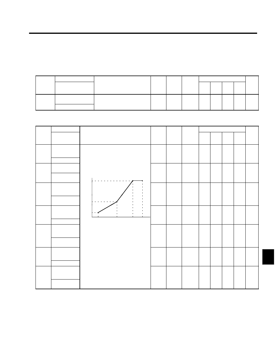
Motor 2 V/f Pattern: E4
Consta
Name
S tti
F t
Change
Control Methods
Consta
nt
Num-
ber
Display
Description
Setting
Range
Factory
Setting
Change
during
Opera-
tion
V/f
V/f
with
PG
Open
Loop
Vector
Flux
Vector
Page
E4-01
Motor 2 max.
output frequen-
cy
50.0 to
150.0
60.0
x
A
x
A
x
6 - 24
V/F2 Max Freq
150.0
E4-02
Motor 2 max.
voltage
0.0 to
510.0
400
x
A
x
A
x
6 24
E4-02
V/F2 Max Volt-
age
Output voltage (V)
VMAX
(E4-02)
510.0
*1
400
*1
x
A
x
A
x
6 - 24
E4-03
Motor 2 max.
voltage fre-
quency
(E4-02)
0.0 to
150 0
60.0
x
A
x
A
x
6 - 24
E4 03
V/F2 Base
Freq
VC
(E4-05)
150.0
60.0
x
A
x
A
x
6 - 24
E4-04
Motor 2 mid.
output frequen-
cy 1
(E4 05)
VMIN
(E4-07)
Fre-
quency
(Hz)
0.0 to
150.0
3.0
*2
x
A
x
A
x
6 - 24
V/F2 Mid Freq
FMIN
(E4-06)
FB
(E4-04)
FA
(E4-03)
FMAX
(E4-01)
150.0
2
E4-05
Motor 2 mid.
output frequen-
cy voltage 1
;
To set V/f characteristics in a straight
line, set the same values for E4-04 and
(E4-06)
(E4-04) (E4-03) (E4-01)
0.0 to
510.0
22.0
*1
x
A
x
A
x
6 - 24
E4 05
V/F2 Mid Volt-
age
line, set the same values for E4-04 and
E4-06. In this case, the setting for
E4-05 will be disregarded.
Always ensure that the four frequen-
5 0.0
*1
*1
x
A
x
A
x
6 - 24
E4-06
Motor 2 min.
output frequen-
cy
Always ensure that the four frequen-
cies are set in the following manner:
E4-01 (FMAX) ≧ E4-03 (FA) >
E4-04 (FB) ≧ E4-06 (FMIN)
0.0 to
150.0
0.5
*2
x
A
x
A
x
6 - 24
V/F2 Min Freq
0 (
) ≧
06 (
)
150.0
2
E4-07
Motor 2 min.
output frequen-
cy voltage
0.0 to
510.0
4.0
*1
x
A
x
A
x
6 - 24
E4 07
V/F2 Min Volt-
age
5 0.0
*1
*1
x
A
x
A
x
6 - 24
* 1. These are values for a 400-V class Inverter. Multiply the values by approx. 1.5 for the 575-V class Inverter.
* 2. When the control method is changed, the Inverter reverts to factory settings. (The open loop vector control factory settings will
be displayed.)
8