Conditions for monitoring – Yaskawa G5HHP Drive User Manual
Page 82
Setting User Constants
4.2.4 Operation Mode
4 - 14
J
Conditions for Monitoring
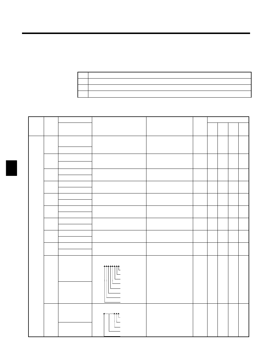
Table 4.3 shows the items that can be monitored in operation mode.
The “Valid access levels” column in the table indicates whether an item can be monitored in a particular
access level and control method. The codes in this column have the following meanings.
Q
Items that can be monitored in all access levels (Quick-Start, Basic, and Advanced).
B
Items that can be monitored in the Advanced and Basic access levels.
A
Items that can be monitored only in the Advanced access level.
x
Items that cannot be monitored in the control mode shown.
The output signal levels for multi-function analog outputs shown in the table are for a gain of 100.0 and a
bias of 0.00.
Table 4.3 Constants Monitored in Operation Mode
Con-
Name
Output Signal Levels for
Valid Access Levels
Func-
tion
Con-
stant
No.
Digital Operator
Display
Function
Output Signal Levels for
Multi-function Analog
Outputs
Min.
Unit
V/f
V/f w/
PG
Open
-loop
Vec-
tor
Flux
Vec-
tor
U1-01
Frequency refer-
ence
Monitors/sets the frequency refer-
ence value.
Th displ
nits c n b s t ith
10 V: Max. frequency
(0 to ±10 V possible)
0.01
Hz
Q
Q
Q
Q
U1 01
Frequency Ref
The display units can be set with
user constant o1-03.
(0 to ±10 V possible)
Hz
Q
Q
Q
Q
U1-02
Output frequency
Monitors the output frequency.
The display units can be set with
10 V: Max. frequency
0.01
Q
Q
Q
Q
U1-02
Output Freq
The display units can be set with
user constant o1-03.
10 V: Max. frequency
(0 to ±10 V possible)
0.01
Hz
Q
Q
Q
Q
U1-03
Output current
Monitors the output current
10 V: Rated current
0 1 A
Q
Q
Q
Q
U1-03
Output Current
Monitors the output current.
10 V: Rated current
(0 to +10 V output)
0.1 A
Q
Q
Q
Q
U1-04
Control method
Shows which control mode is set
Can’t be output
Q
Q
Q
Q
U1-04
Control Method
Shows which control mode is set. Can’t be output.
--
Q
Q
Q
Q
U1-05
Motor speed
Monitors the motor speed
10 V: Max. frequency
0.01
X
Q
Q
Q
U1-05
Motor Speed
Monitors the motor speed.
10 V: Max. frequency
(0 to ±10 V possible)
0.01
Hz
X
Q
Q
Q
U1-06
Output voltage
Monitors the Inverter’s internal
10 V: 400 (575) VAC
0 1 V
Q
Q
Q
Q
U1-06
Output Voltage
Monitors the Inverter s internal
output voltage reference value.
10 V: 400 (575) VAC
(0 to +10 V output)
0.1 V
Q
Q
Q
Q
U1-07
DC bus voltage
Monitors the DC voltage of the
10 V: 500 (1040) VDC
1 V
Q
Q
Q
Q
U1-07
DC Bus Voltage
Monitors the DC voltage of the
Inverter’s internal main circuit.
10 V: 500 (1040) VDC
(0 to +10 V output)
1 V
Q
Q
Q
Q
Status
Moni
U1-08
Output power
Monitors the output power. (This
10 V: Max. motor capacity
0 1 kW
Q
Q
Q
Q
Moni-
tor
U1-08
Output kWatts
Monitors the output power. (This
is an internally detected value.)
10 V: Max. motor capacity
(0 to ±10 V possible)
0.1 kW
Q
Q
Q
Q
tor
U1-09
Torque reference
Monitors the internal torque refer-
ence value when vector control is
10 V: Rated torque
0 1 %
X
X
Q
Q
U1-09
Torque Reference
ence value when vector control is
used.
10 V: Rated torque
(0 to ±10 V possible)
0.1 %
X
X
Q
Q
U1-10
Input terminal sta-
tus
Shows input ON/OFF status.
U1-10 = 0 0 0 0 0 0 0 0
1: Terminal 9 ON
1: Terminal 10 ON
1: Terminal 11 ON
Can’t be output.
--
Q
Q
Q
Q
U1 10
Input Term Sts
1: Terminal 12 ON
1: Terminal 13 ON
1: Terminal 14 ON
1: Terminal 15 ON
1: Terminal 16 ON
Can t be output.
--
Q
Q
Q
Q
U1-11
Output terminal
status
Shows output ON/OFF status.
U1-11 = 0 0 0 0 0 0 0 0
1: Terminals 53--57 ON
1: Terminal 19 ON
Can’t be output.
--
Q
Q
Q
Q
U1 11
Output Term Sts
1: Terminal 19 ON
1: Terminal 20 ON
Not used. (always 0)
1: Terminals 25/52--23 ON
Can t be output.
--
Q
Q
Q
Q
4