3 torque control, Torque control function settings: d5-01 – Yaskawa G5HHP Drive User Manual
Page 183
7.3 Flux Vector Control
7 - 19
D
To output the zero-servo status externally, assign the Zero Servo End signal (setting 33) to one of the
multi-function outputs (H2-01 to H2-03). The setting in b9-02 (Zero-servo Completion Width) is en-
abled when one of the multi-function outputs has been set to 33.
D
The Zero Servo End signal remains ON as long as the position is within this range (starting position ±
Zero-servo Completion Width).
D
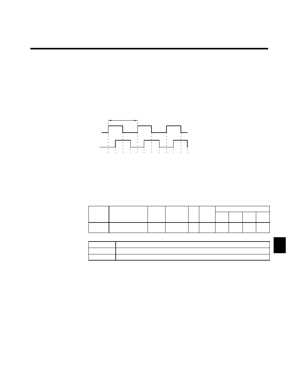
Set the Zero-servo Completion Width to four times the number of pulses from the PG (pulse generator
or encoder), as shown in Figure 7.8.
For example, when a 600 p/r encoder is being used, the number of pulses would be 2,400 p/r after multi-
plying by four.
D
The Zero Servo End signal will go OFF when the zero servo command is turned OFF.
D
Do not lock the servo for extended periods of time at 100% when using the zero servo function. Extended
periods of servo lock can be achieved by ensuring that the current during the servolock is 50% or less
or by increasing the Inverter capacity.
Phase A
Phase B
1 pulse
Count
1
2
3
4
5 6
7
8
9 10 11 12
Factor of 4: By counting the rising and
falling edges of phase A
this method has four times
the resolution of the PG.
Fig 7.8
Pulse Count Factored by 4
7.3.3 Torque Control
J
Torque Control Function Settings: d5-01
With flux vector control, the motor’s output torque can be controlled by a torque reference from an analog
input.
User
Change
during
Setting
Factory
Valid Access Levels
User
Constant
Number
Name
g
during
Opera-
tion
Setting
Range
Unit Factory
Setting
V/f
Control
V/f with
PG
Open
Loop
Vector
Flux
Vector
d5-01
Torque control selec-
tion
x
0, 1
--
0
x
x
x
A
D
Settings
Setting
Function
0
Speed control (controlled by C5-01 to C5-07)
1
Torque control
D
Set constant d5-01 to “1” to select torque control.
D
Figure 7.9 shows the operation of torque control.
7