Yaskawa G5HHP Drive User Manual
Page 247
7.5 Common Functions
7 - 83
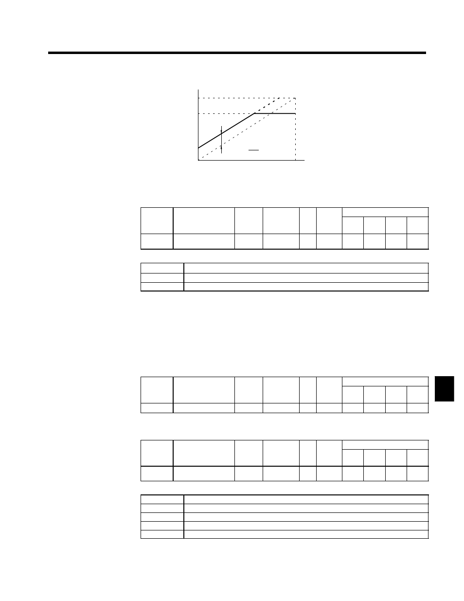
Output voltage
Gain × 10 V
10 V
0 V
Monitored item
0 %
100 %
Bias × 100
10 V
Fig 7.41
Monitor Output Adjustments
Multi-function Analog Output Signal Level: H4-07
User
Change
during
Setting
Factory
Valid Access Levels
User
Constant
Number
Name
g
during
Opera-
tion
Setting
Range
Unit Factory
Setting
V/f
Control
V/f with
PG
Open
Loop
Vector
Flux
Vector
H4-07
Analog output signal
level selection
x
0, 1
--
0
B
B
B
B
D
Settings
Setting
Function
0
0 to +10 V (Absolute value output)
1
0 to
±
10 V
D
This signal level setting applies to analog outputs 1 and 2 (terminals 45 and 48).
D
When the 0 to ±10 V signal level is used to output speed values (frequency reference, output frequency,
or motor speed), positive voltage indicates Inverter output in the forward direction and negative voltage
indicates Inverter output in the reverse direction. (Assuming a bias setting of 0.0.)
D
There are some monitor items that are limited to the 0 to +10 V signal range even when the 0 to ±10 V
signal level has been selected. Refer to Table 4.3 Status Monitor Items for details.
J
MEMOBUS Communications Settings: H5-01 to H5-05
Station Node Address: H5-01
D
Set the Inverter node address.
User
Change
during
Setting
Factory
Valid Access Levels
User
Constant
Number
Name
g
during
Opera-
tion
Setting
Range
Unit Factory
Setting
V/f
Control
V/f with
PG
Open
Loop
Vector
Flux
Vector
H5-01
Station address
x
0 to 20
--
1F
A
A
A
A
Baud Rate: H5-02
D
Set the baud rate for MEMOBUS communications.
User
Change
during
Setting
Factory
Valid Access Levels
User
Constant
Number
Name
g
during
Opera-
tion
Setting
Range
Unit Factory
Setting
V/f
Control
V/f with
PG
Open
Loop
Vector
Flux
Vector
H5-02
Communication speed
selection
x
0 to 3
--
3
A
A
A
A
D
Settings
Setting
Baud Rate
0
1200 bps
1
2400 bps;
2
4800 bps
3
9600 bps
7