Yaskawa G5HHP Drive User Manual
Page 290
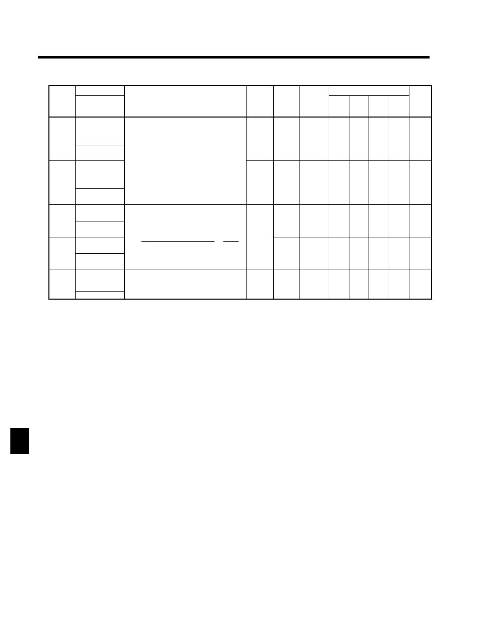
User Constants
8.2.5 Options Constants: F
8 - 24
Consta
nt
Num-
ber
Page
Control Methods
Change
during
Opera-
tion
Factory
Setting
Setting
Range
Description
Name
Consta
nt
Num-
ber
Page
Flux
Vector
Open
Loop
Vector
V/f
with
PG
V/f
Change
during
Opera-
tion
Factory
Setting
Setting
Range
Description
Display
F1-10
Excessive
speed devi-
ation detection
level
Sets the speed deviation detection method.
Any speed deviation above the F1-10 set lev-
0 to 50
10
x
x
A
x
A
6 - 28
6 - 42
PG Deviate
Level
Any speed deviation above the F1 10 set lev
el (set as a percentage of the maximum out-
put frequency), which continues for the devi-
ation detection time (F1-11) is detected as a
6 - 42
F1-11
Excessive
speed devi-
ation detection
delay time
ation detection time (F1-11) is detected as a
speed deviation.
;
Speed deviation is the difference between
actual motor speed and the reference com-
mand speed.
0.0 to
10.0
0.5
x
x
A
x
A
6 - 28
6 - 42
PG Deviate
Time
mand speed.
10.0
6 - 42
F1-12
Number of PG
gear teeth 1
Sets the number of teeth on the gears if there
are gears between the PG and the motor.
0
x
x
A
x
x
6 41
F1-12
PG# Gear
Teeth 1
Motor speed (r∕min)
Load gear teeth
No. of pulses input PG × 60
F1 13
0 to
1000
0
x
x
A
x
x
6 - 41
F1-13
Number of PG
gear teeth 2
Motor gear teeth
=
No. of pulses input PG × 60
No. of PG pulses(F1-01) ×
F1-13
F1-12
0 to
1000
0
x
x
A
x
x
6 41
F1-13
PG# Gear
Teeth 2
Motor gear teeth
;
A gear ratio of 1 will be used if either of
these constants is set to 0.
0
x
x
A
x
x
6 - 41
F1-14
PG open-cir-
cuit detection
time
Used to set the PG disconnection detection
time. PGO will be detected if the detection
time continues beyond the set time
0.0 to
10.0
2.0
x
x
A
x
A
6 - 27
PGO Time
time continues beyond the set time.
10.0
* The setting range will change when the control method is changed. (The setting range for Open loop vector control will be dis-
played.)
8