Trigger limits, Ii – 3 s w itc h ing inputs and outputs – HEIDENHAIN ND 287 User Manual User Manual
Page 96
96
II Installation, specifications
II – 3 S
w
itc
h
ing inputs and outputs
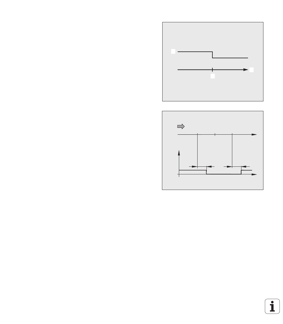
Trigger limits
As soon as the trigger limit
1
defined by parameter is reached (see
figure at right), the corresponding output
2
is activated (3: path). You
can set up to two trigger limits: A1 and A2 (see "Switching signals" on
page 38). A separate output is available for the zero crossover (see
"Zero crossover" on page 97).
In the Distance-To-Go operating mode, switching outputs A1 (pin 15)
and A2 (pin 16) have a different function: They are symmetrical about
zero. For example, if a trigger point of 10 mm is entered for A1, then
output A1 switches at both +10 mm and -10 mm. Fig. II.62 shows
output signal A1 when traversing to display value zero from the
negative direction: A1 = 10 mm, t
V1
≤
30 ms, t
V2
≤
180 ms.
Fig. II.61 Trigger limit A1
Fig. II.62 Time curve of signal at pin 15 for trigger
limit A1 = 10 mm
1
1
1
2
1
3
-10
s
t
t
v2
t
v1
Pin 15
(A1)
10
0