Ii – 3 switching inputs and outputs, Switching inputs at d-sub connection x41 – HEIDENHAIN ND 287 User Manual User Manual
Page 93
ND 287
93
II – 3 S
w
itc
h
ing inputs and outputs
II – 3 Switching inputs and outputs
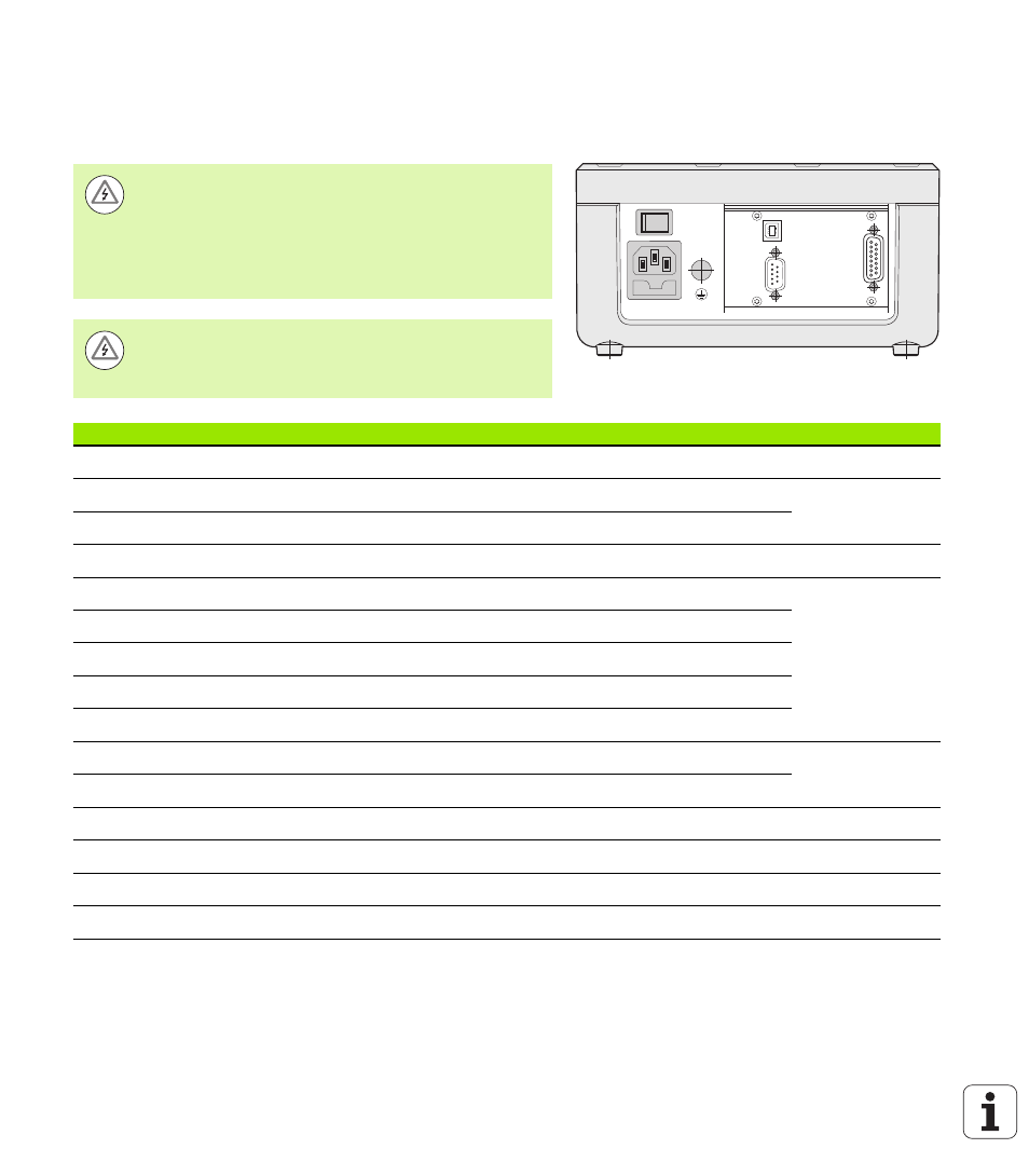
Switching inputs at D-sub connection X41
Fig. II.58 Connections
X1
X32/X31
Danger to internal components!
The power supply of external circuits must comply with
EN 50178 requirements for low voltage electrical
separation
.
Connect inductive loads only with a quenching diode
parallel to the inductance
.
Danger to internal components!
Use only shielded cables and connect the shield to the
connector housing
.
Pin
Function
See page
1, 10
0 V
2
Reset to zero, clear error message
3
Set axis / coupled axes to value for datum point
4
Ignore reference mark signals (X1)
5
Start series of measurements / f(X1,X2) display
6
Externally select display value for series of measurements / X1 display
7
Display minimum value of series of measurements / X2 display
8
Display maximum value of series of measurements / X1+X2 display
9
Display difference MAX-MIN of series of measurements / X1-X2 display
22
Pulse: Transmit measured value
Page 94 and
23
Contact: Transmit measured value
24
Ignore reference mark signals (X2, optional)
25
Enable or disable REF mode (current REF status is changed)
12, 13
Do not assign
11, 20, 21
Vacant