Ii – 1 installation and electr ical connection – HEIDENHAIN ND 287 User Manual User Manual
Page 69
ND 287
69
II – 1 Installation and electr
ical connection
Pin assignment X1/X2
Optional: Analog module with ±10 V interface at input X1 or X2
for connecting an analog sensor
For example, you can connect an analog linear encoder to this
connection, or a temperature sensor with a voltage interface to X2.
The ND converts the voltage value to a readable measured value.
A separate description of the analog module is included with the
module.
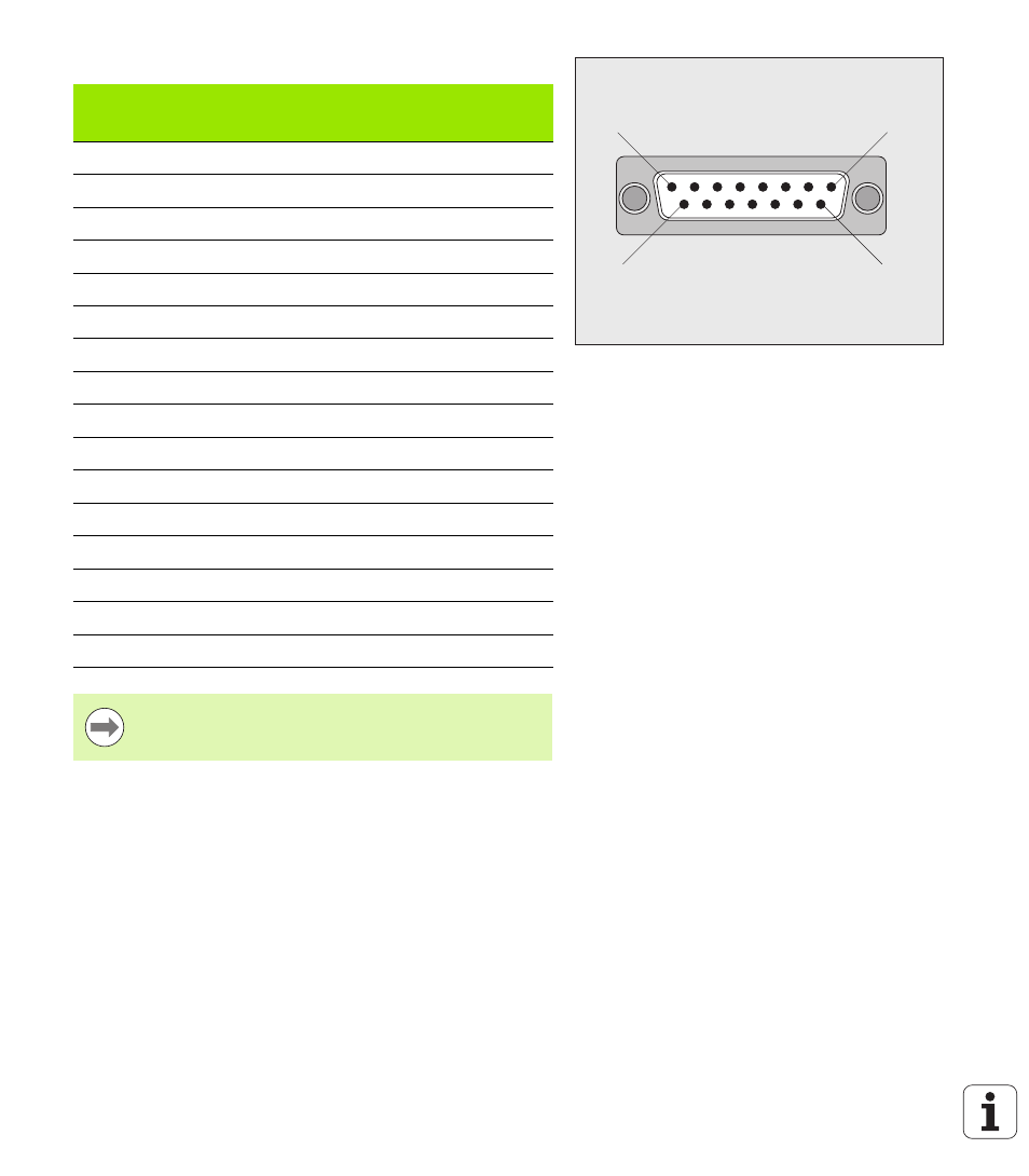
Fig. II.6
15-pin encoder connector X1 or X2 for the
encoder input on the rear panel
1
8
9
15
D-sub
connector
15-pin
Input signal
11 µApp
Input signal
1 Vpp
EnDat
(purely serial)
1
I1+
A+
2
0 V (UN)
0 V (UN)
0 V (UN)
3
I2+
B+
4
5 V (Up)
5 V (Up)
5 V (Up)
5
Data
6
Internal shield
7
I0–
R–
8
Clock
9
I1–
A–
10
0 V sensor
0 V sensor
11
I2–
B–
12
5 V sensor
5 V sensor
13
Data (inverse)
14
I0+
R+
15
Clock (inverse)
Housing
External shield
External shield
External shield
In the INSTALLATION SETUP menu, you define the
parameters for the encoder (see "Setting up the encoder"