Input signals, Signal level of inputs, Ignoring the reference mark signals – HEIDENHAIN ND 287 User Manual User Manual
Page 94: Ii – 3 s w itc h ing inputs and outputs
94
II Installation, specifications
II – 3 S
w
itc
h
ing inputs and outputs
Input signals
Signal level of inputs
Ignoring the reference mark signals
If the input at pin 4 is active, the ND will ignore the reference mark
signals of axis X1. If the input at pin 24 is active, the ND will ignore
the reference mark signals of axis X2 (optional). A typical application
of this function is for measuring lengths with a rotary encoder and
leadscrew; in this case, a cam switch releases the reference mark
signal at a preset position.
Special case:
If you want to display the current measured value ACTL
of a measurement series, the following applies for inputs
7
, 8 and 9: Either none or more than one of these inputs
must be active.
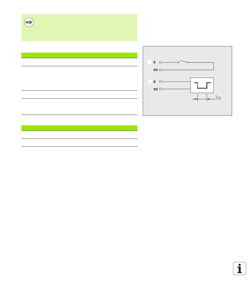
Fig. II.59 Switching inputs for measured value
output at X41; 1: Contact (pin 23), 2:
Pulse (pin 22)
1
1
1
2
Signal
Value
Internal pull-up resistor
1 k
Ω,
active Low
Activation
Trigger by making contact
against 0 V or by low-level signal
over TTL logic device (see
"Measured value output after a
Delay time for preset/reset
t
V
≤
2 ms
Minimum pulse duration for all
signals (except for pin 22 and
pin 23, see Page 113)
t
min
≥
30 ms
Status
Level
High
+3.9 V
≤
U
≤
+15 V
Low
–0.5 V
≤
U
≤
+0.9 V; I
≤
6 mA