Wiring the connecting cable, Ii – 5 d a ta int e rf ace – HEIDENHAIN ND 287 User Manual User Manual
Page 104
104
II Installation, specifications
II – 5 D
a
ta int
e
rf
ace
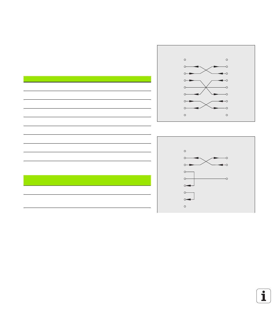
Wiring the connecting cable
The wiring of the connecting cable depends on the device being
connected (see technical documentation for external device).
Complete wiring of RS-232-C/V.24 (X31)
Before the ND 287 and your PC can communicate, they need to be
connected to each other with a serial cable.
RS-232-C / V.24 data transfer cable
D-sub (female) 9-pin/D-sub (female) 9-pin
ID 366964-xx
Signal level
Fig. II.70 Pin assignment for serial port with
handshaking
Fig. II.71 Pin assignment for serial port without
handshaking
NC 1
RxD 2
TxD 3
DTR 4
GND 5
DSR 6
RTS 7
CTS 8
NC 9
1 NC
2 RxD
3 TxD
4 DTR
5 GND
6 DSR
7 RTS
8 CTS
9 NC
ND 28x
D9
NC 1
RxD 2
TxD 3
DTR 4
GND 5
DSR 6
RTS 7
CTS 8
NC 9
2 RxD
3 TxD
5 GND
ND 28x
D9
Pin
Assignment
Function
1
Do not assign
3
TXD
Transmitted data
2
RXD
Received data
7
RTS
Request to send
8
CTS
Clear to Send
6
DSR
Data set ready
5
SIGNAL GND
Signal ground
4
DTR
Data terminal ready
9
Do not assign
Signal
Signal level
"1" = "active"
Signal level
"0"= "inactive"
TXD, RXD
–3 V to –15 V
+3 V to +15 V
RTS, CTS
DSR, DTR
+3 V to +15 V
–3 V to –15 V