Switching signals, I – 4 j o b set u p – HEIDENHAIN ND 287 User Manual User Manual
Page 38
38
I Working with the ND 287 position display unit
I – 4 J
o
b Set
u
p
Switching signals
In the JOB SETUP menu, use the DOWN arrow key to select
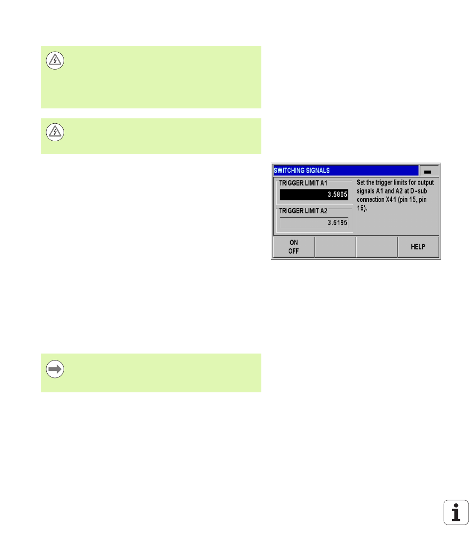
SWITCHING SIGNALS, and press the ENTER key to open the form.
Press the ON/OFF soft key to activate/deactivate the trigger points.
Using the numeric keys, enter the desired trigger limits A1 and A2.
When the trigger limits defined by parameter are reached, the
corresponding output becomes active. Output A1 represents pin 15
at D-sub connection X41, and output A2 represents pin 16:
Pin 15
remains active as long as the measured value is greater than
or equal to A1
.
Pin 16
remains active as long as the measured value is greater than
or equal to A2
.
A separate output is available for trigger point zero. If the display value
is zero, the position display unit always activates pin 14 at D-sub
connection X41. The minimum signal duration is 180 ms.
The ND 287 constantly monitors the measuring signal, the input
frequency, the data output, etc., and displays errors in the message
line. If errors occur that seriously influence measurement or data
output, the ND activates the switching output at pin 19. The output
remains active until the error has been acknowledged. This makes it
possible to monitor proper function during automated processes.
Danger to internal components!
The power supply of external circuits must comply with
EN 50178 requirements for low voltage electrical
separation.
Connect inductive loads only with a quenching diode
parallel to the inductance
.
Danger to internal components!
Use only shielded cables and connect the shield to the
connector housing
.
Fig. I.31 Switching signals
In the Distance-To-Go operating mode, the switching
outputs A1 (pin 15) and A2 (pin 16) have a different
function
(see "Switching outputs at D-sub connection
X41" on page 95).