Ii – 6 measured value output, Alternatives for starting measured value output, Measured value output after a trigger signal – HEIDENHAIN ND 287 User Manual User Manual
Page 113: Propagation times, Duration of measured value transfer, Measured value output after a, Measured value
ND 287
113
II – 6 Measur
ed v
alue output
II – 6 Measured value output
Alternatives for starting measured value output
With a PC, there are three different ways to start measured value
output from the ND 287:
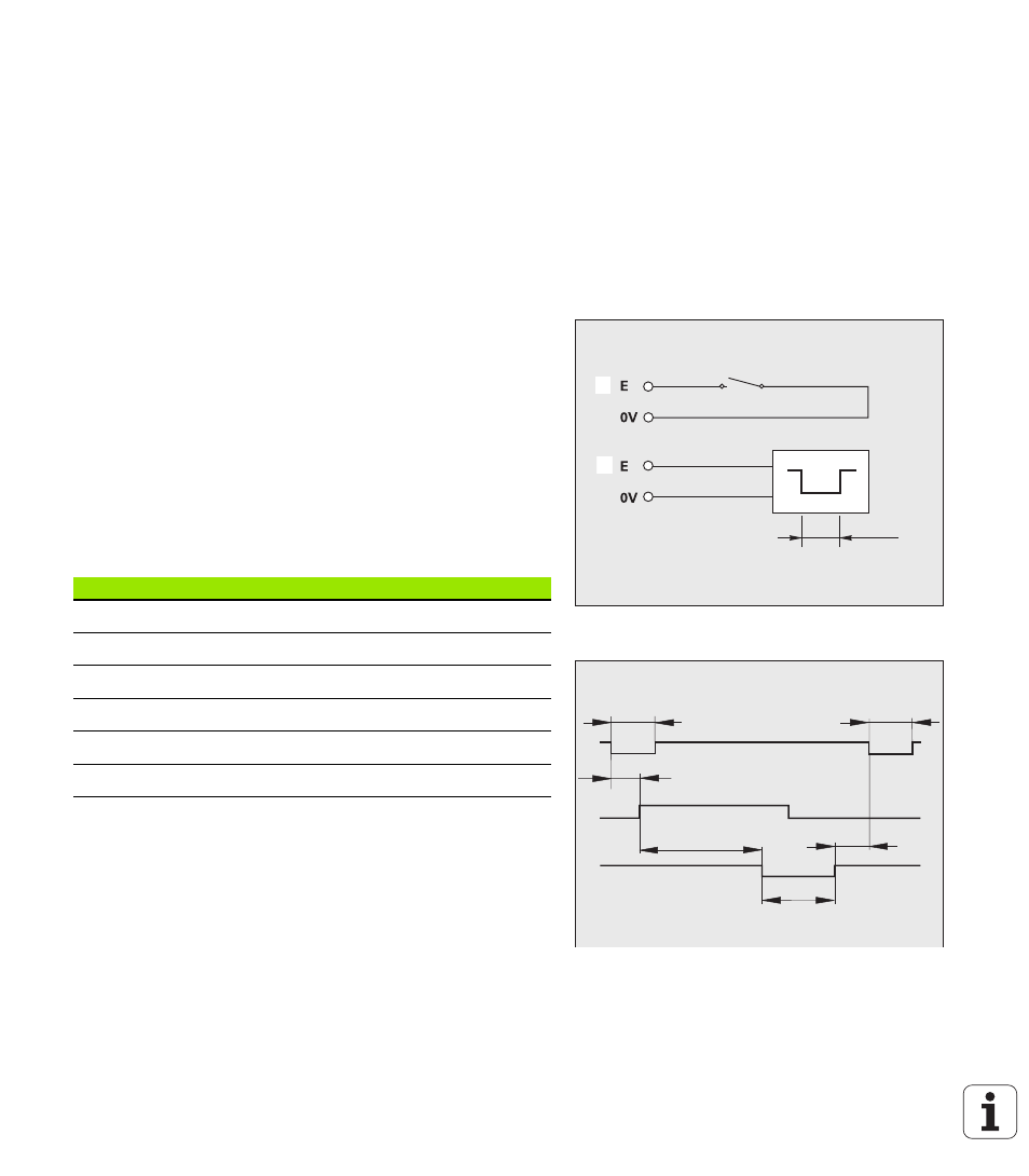
After a trigger signal at input X41 (see "Switching inputs at D-sub
With CTRL B or the PRINT soft key over the serial port X31 or X32
Measured value output after a trigger signal
There are two ways to start measured value output over the interface
(X41) (see Fig. II.73):
Connect the Contact input (pin 23 at X41) to pin 1 or pin 10 (0 V)
via a standard switch.
Or: Connect the Pulse input (pin 22 at X41) to pin 1 or pin 10 (0 V)
via a TTL logic device (such as SN74LSXX). Measured-value output
is triggered by a pulse.
The ND 287 transmits the measured values according to the
parameters defined in the JOB SETUP menu (see "Measured-value
output" on page 39) via the TXD line of the RS-232-C/V.24 interface or
the USB interface.
Propagation times
Duration of measured value transfer
Fig. II.73 Switching inputs for measured value
output at X41; 1: Contact, 2: Pulse
Fig. II.74 Propagation times for measured value
output after contact or pulse
t
e
1
1
1
2
t
1
t
2
t
e
t
e
t
D
t
3
Event
Time
Minimum duration t
e
of Contact signal
t
e
≥
7 ms
Minimum duration t
e
of Pulse signal
t
e
≥
1.5 µs
Latching delay t
1
after Contact
t
1
≤
5 ms
Latching delay t
1
after Pulse
t
1
≤
1 µs
Measured-value output after t
2
t
2
≤
50 ms
Regeneration time t
3
t
3
≥
0 ms
t
D
: Duration of measured value transfer in [s]
L: Number of blank lines
B: Baud rate
t
D
187
11 L
•
(
)
+
B
----------------------------
=