Function of external inputs, I – 4 j o b set u p – HEIDENHAIN ND 287 User Manual User Manual
Page 40
40
I Working with the ND 287 position display unit
I – 4 J
o
b Set
u
p
Function of external inputs
Use FUNCTION EXT. INPUTS in the JOB SETUP menu to determine
the ND 287's reaction to the external inputs at connection X41 (see
"Switching inputs at D-sub connection X41" on page 93).
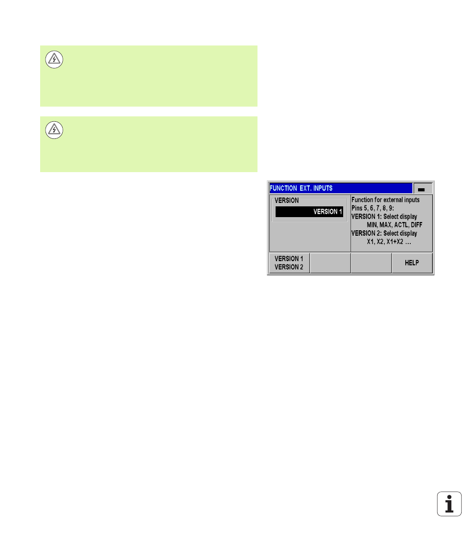
In the JOB SETUP menu, select FUNCTION EXT. INPUTS and press
the ENTER key to open the form.
Press the VERSION soft key. Two different versions are available:
VERSION 1: You can externally activate the minimum/
maximum measurement for measurement series
if the signal
at pin 6 remains permanently LOW. The SELECT DISPLAY soft
key for selecting the display mode becomes ineffective. Pin 7
sets the display to MIN, pin 8 to MAX and pin 9 to DIFF. The
display can only be set to ACTL if either none of the pins 7, 8 or 9
or more than one of the pins carries a signal. A signal (pulse) at
pin 5
starts a new series of measurements if the signal at pin 6
is permanently LOW.
VERSION 2: If pins 5, 6, 7, 8 or 9 are activated, the display modes
are switched to operation with two axes
. Pin 6 switches to
axis X1, pin 7 to axis X2, pin 8 to the sum of the two axes X1+X2,
pin 9
to the difference between the two axes X1-X2 and pin 5
switches to the definable relationship between the two axes
f(X1,X2)
, see "Formula for coupled position" on page 78.
An overview of the switching inputs and outputs is provided on
Danger to internal components!
The power supply of external circuits must comply with
EN 50178 requirements for low voltage electrical
separation
.
Connect inductive loads only with a quenching diode
parallel to the inductance
.
Danger to internal components!
Use only shielded cables and connect the shield to the
connector housing
.
The function for hiding possible display modes of the axes
(see page 78) is always active.
Fig. I.33 External inputs function