Preventative maintenance or repair, Connecting the encoders, Ii – 1 installation and electr ical connection – HEIDENHAIN ND 287 User Manual User Manual
Page 68
68
II Installation, specifications
II – 1 Installation and electr
ical connection
Preventative maintenance or repair
No special preventative maintenance is necessary. For cleaning, wipe
lightly with a dry lint-free cloth.
Connecting the encoders
The ND 287 operates with the following encoders:
Incremental encoders with sinusoidal output signals (11 µApp or
1 Vpp interface)
Absolute encoders with a bidirectional EnDat interface (purely serial;
when an EnDat 2.1 interface is used, the resolution is limited,
because the incremental signals are ignored.)
Optional: Analog sensor with ±10 V interface
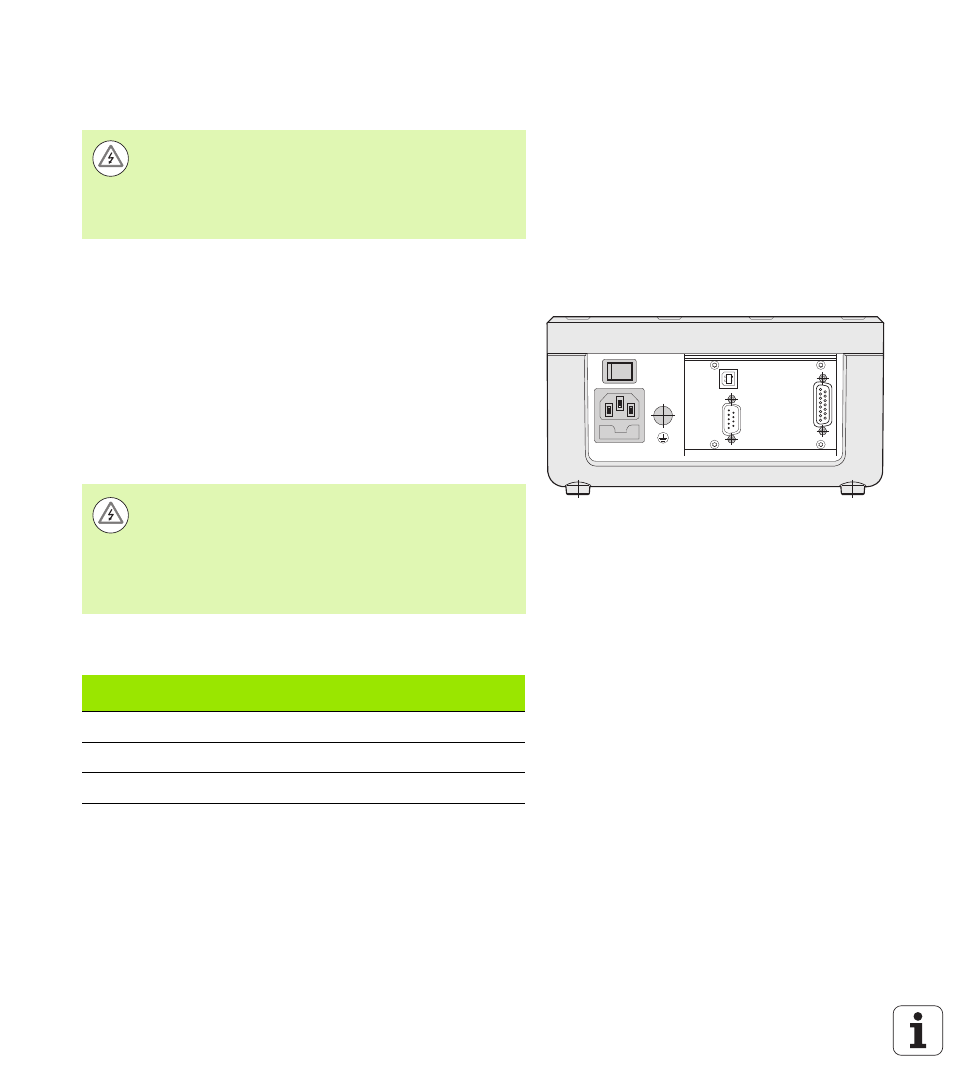
The slots for the encoder input assemblies on the rear panel are
designated X1 and X2.
D-sub connection X1/X2 (15-pin, female) for the following input
signals
Danger of electrical shock!
The position display unit must be repaired by qualified
and authorized service technicians.
See the last page of the Operating Instructions for our
service department's contact data.
Fig. II.5
Connections
X1
X32/X31
Danger of electrical shock!
The interfaces X1 and (optionally) X2 comply with the
requirements of EN 50 178 for low voltage electrical
separation
.
Do not engage or disengage any connecting elements
while the unit is under power!
Input signal
Maximum
cable length
Maximum input
frequency
11 µApp
30 m
100 kHz
1 Vpp
60 m
500 kHz
EnDat
100 m
-