Ii – 2 installation set u p – HEIDENHAIN ND 287 User Manual User Manual
Page 75
ND 287
75
II – 2 Installation Set
u
p
Analog sensor with ±10 V interface, preferably a temperature
sensor
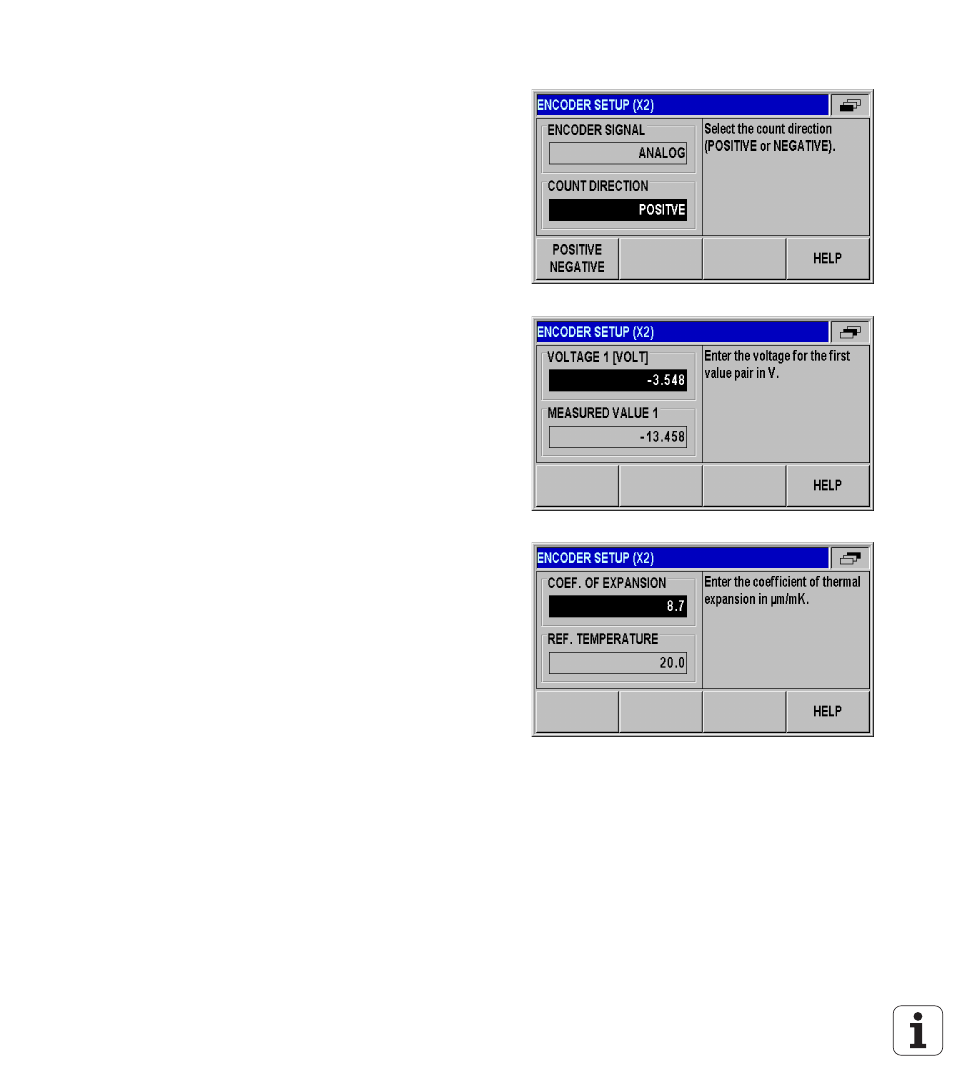
In the COUNT DIRECTION field, select the count direction by
pressing the POSITIVE/ NEGATIVE soft key. If the encoder's count
direction matches the user's traverse direction, select POSITIVE. If
the directions do not match, select NEGATIVE.
In the four following fields, enter any two voltage/measured-value
pairs for the correct definition of the analog sensor: At first, enter the
values in the VOLTAGE 1 and MEASURED VALUE 1 fields, and then
in the VOLTAGE 2 and MEASURED VALUE 2 fields. The ND 287
uses the values to calculate a linear relationship between input
voltage and measured value in the range from –10 V to +10 V. To
ensure the highest possible measuring accuracy, enter the voltage
values with an accuracy of 5 mV.
If you have selected COMPENSATION for INPUT X2 in the
ENCODER TYPE field in the ENCODER SETUP menu, two further
parameters for defining temperature-dependent axis-error
compensation are displayed.
In the COEF. OF EXPANSION field, enter a value for the coefficient
of expansion E in µm/mK.
In the REF. TEMPERATURE field, enter the temperature T
R
to be
deducted from the measured temperature.
The axis-error compensation is calculated according to the following
formula:
L_1 = L_0 * (1 + E * (T - T
R
))
L_1: Compensated linear value of the encoder at input X1 after
axis-error compensation
L_0: Displayed linear value of the encoder at input X1 without
compensation
E: Coefficient of expansion in µm/mK
T: Temperature measured in °C
T
R
: Defined reference temperature in °C
Press ENTER to confirm your entry.
The ND 287 constantly displays the measured temperature on the
left side of the message line.
Fig. II.19 Analog sensor form
Fig. II.20 Analog sensor form
Fig. II.21 Temperature sensor form