The vizrt graphic configuration panel, The vertigoxg panel – Grass Valley iTX System v.2.6 User Manual
Page 181
Configuring channel plug-ins
To test the Clarity character generator configuration, you click Test. The test results are
displayed in the Clarity Test Report dialog. When the test is finished, click Close to close the
dialog.
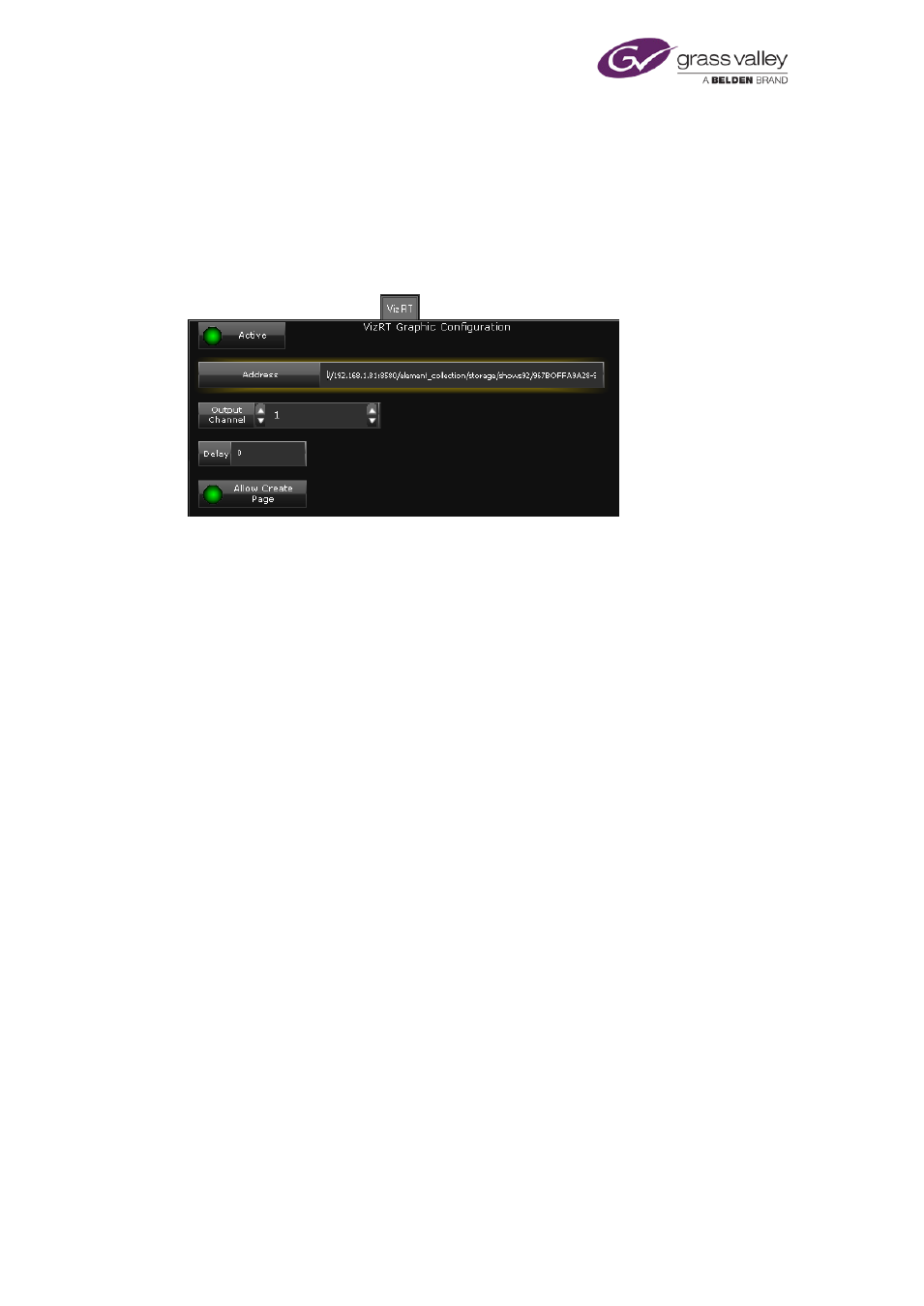
The VizRT Graphic Configuration panel
You set up iTX to work with a VizRT character generator through the VizRT Graphic
Configuration panel:
Select Active to use the VizRT character generator with the channel. This allows an operator to
create a CG event using a page in the VizRT character generator.
In the Address box, enter the address of the VizRT device. This typically consists of a number of
elements:
•
The IP address of the VizRT device and the port number that it uses for communications
with iTX.
•
The path of the directory that stores the pages that are to be available for VizRT events.
•
The name of template that may be used for creating pages that do not exist.
To allow the VizRT device to create pages that do not exist, you select Allow Create Page.
The Output Channel and Delay boxes are not currently used.
The VertigoXG panel
The branding capabilities of a typical iTX playout channel can be enhanced by integrating
Vertigo graphics events into the iTX playout schedule. Using the VertigoXG plugin, Vertigo XG
events can be added to the iTX Desktop’s schedule as secondary graphics events and then
inserted into the iTX program stream either using:
•
the XG Inside as an option that integrates the XG Renderer directly within iTX Output
Servers and iTX Playout Appliances
or,
•
an external Grass Valley Vertigo XG device downstream of the iTX Output Server.
For more information about configuring Vertigo XG, see the Vertigo XG & iTX Integration User
Guide.
March 2015
System Administrator Guide
Page 181 of 404