2 rear panel – Comtech EF Data CDM-600/600L User Manual
Page 37
CDM-600/600L Open Network Satellite Modem
Revision 3
Introduction
MN/CDM600L.IOM
1–9
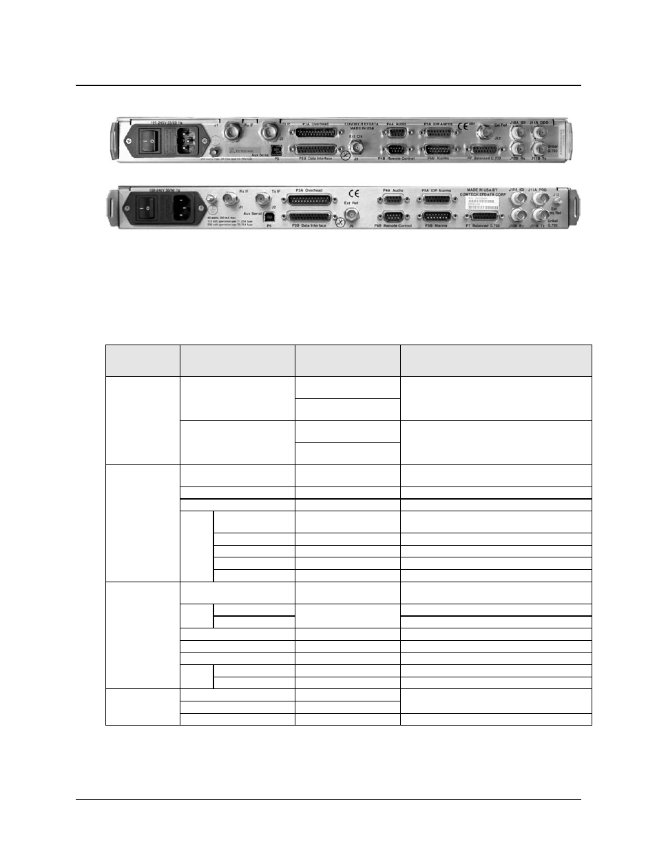
1.3.5.2 Rear Panel
Figure 1-6. Rear Panel View
Figure 1-6 shows the connectors installed in the rear panel of the CDM-600/600L Open Network
Satellite Modem. Each connector outlined in Table 1-1 is described in detail in Chapter 3.
REAR PANEL CONNECTOR PINOUTS. External cables are attached to these connectors.
Table 1-1. CDM-600/600L Rear Panel Connectors
Connector Group
(Chapter 3
Sect. Ref.)
Ref Des / Name
Connector Type
Function
IF
(Sect. 3.2)
J1 Rx
CDM-600L: Type ’N’ female
(L-Band)
IF Input
CDM-600: BNC female
(70/140MHz band)
J2 Tx
CDM-600L: Type ’N’ female
(L-Band)
IF Output
CDM-600: BNC female
(70/140MHz band)
Terrestrial Data
(Sect. 3.3)
P3A Overhead
25-pin Type ‘D’ male
INTELSAT overhead – 64kbps RS-422, 1/16 IBS overhead
ESC @RS-232; IDR backward alarm
P3B Data Interface
25-pin Type ‘D’ female
Serial synchronous data Input/Output
P4A Audio
9-pin Type ‘D’ female
ADPCM audio Input/Output
G.703
Data
P7 Balanced
15-pin Type ‘D’ female
G.703 Balanced T1 (1.544 Mps) / E1 (2.048 Mbps) / T2
(6.312 Mbps)
J10A IDI
BNC 75Ω female
Insert Data In – G.703 Unbalanced E1 (2.048 Mbps)
J11A DDO
BNC 75Ω female
Drop Data Out – G.703 Unbalanced E1 (2.048 Mbps)
J10B Rx
BNC 75Ω female
G.703 Unbalanced E1 (2.048 Mbps) Rx
J11B Tx
BNC 75Ω female
G.703 Unbalanced E1 (2.048 Mbps) Tx
Utility
(Sect. 3.4)
P6 Aux Serial
USB Type ‘B’ female
RS-232 Serial Remote interface for 1:1 Redundant
operations
J9
CDM-600L: Ext Clk
BNC 50Ω female
External Clock Input
CDM-600: Ext Ref
External Reference Input
P4B Remote Control
9-pin Type ‘D’ male
Serial Remote Interface (RS-232/-485)
P5A IDR Alarms
15-pin Type ‘D’ female
Form C Alarms (backward alarm outputs)
P5B Alarms
15-pin Type ‘D’ male
Form C Alarms (relay closures)
J12
CDM-600L: Ext Ref
BNC 50Ω female
External reference for modem synthesizers
CDM-600: Ext Freq Ref SMA female
High-stability External Reference (optional)
Power/Ground
(Sect 3.5)
AC
See Sect. 3.5.1
Chassis power
DC (optional, CDM-600L only)
See Sect. 3.5.2
Ground #10-32
stud
Common Chassis Ground
Note:
The European EMC Directive (EN55022, EN50082-1) requires using properly shielded cables for DATA
I/O. These cables must be double-shielded from end-to-end, ensuring a continuous ground shield.
CDM-600L
CDM-600