Basler Electric DGC-2020HD Modbus Protocol User Manual
Page 264
258
9469300991 Rev A
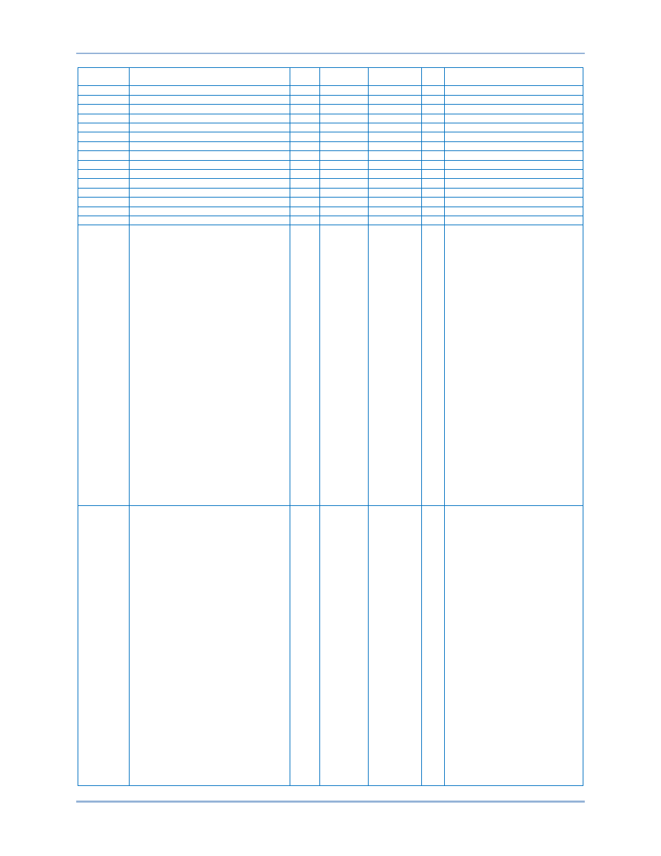
Legacy Register Table
DGC-2020HD Modbus
™ Protocol
Register
Description
Type
Units
Scaling
Factor
R/W
Range
45506
Analog Input 4 Metering Value
Int32
CentiUnit
Centi
R
(-100000000) – 99999900
45508
Analog Input 5 Metering Value
Int32
CentiUnit
Centi
R
(-100000000) – 99999900
45510
Analog Input 6 Metering Value
Int32
CentiUnit
Centi
R
(-100000000) – 99999900
45512
Analog Input 7 Metering Value
Int32
CentiUnit
Centi
R
(-100000000) – 99999900
45514
Analog Input 8 Metering Value
Int32
CentiUnit
Centi
R
(-100000000) – 99999900
45516
RTD Input 1 Metering Value
Int32
CentiDeg F Centi
R
(-100000000) – 99999900
45518
RTD Input 2 Metering Value
Int32
CentiDeg F Centi
R
(-100000000) – 99999900
45520
RTD Input 3 Metering Value
Int32
CentiDeg F Centi
R
(-100000000) – 99999900
45522
RTD Input 4 Metering Value
Int32
CentiDeg F Centi
R
(-100000000) – 99999900
45524
RTD Input 5 Metering Value
Int32
CentiDeg F Centi
R
(-100000000) – 99999900
45526
RTD Input 6 Metering Value
Int32
CentiDeg F Centi
R
(-100000000) – 99999900
45528
RTD Input 7 Metering Value
Int32
CentiDeg F Centi
R
(-100000000) – 99999900
45530
RTD Input 8 Metering Value
Int32
CentiDeg F Centi
R
(-100000000) – 99999900
45532
Thermocouple Input 1 Metering Value
Int32
CentiDeg F Centi
R
(-100000000) – 99999900
45534
Thermocouple Input 2 Metering Value
Int32
CentiDeg F Centi
R
(-100000000) – 99999900
45536-37
AEM Input Threshold Status Bits Reg 1
Uint32 n/a
n/a
R
Bit 0 = Not Used
Bit 1 = Not Used
Bit 2 = Analog Input 6 Under 2
Bit 3 = Analog Input 6 Under 1
Bit 4 = Analog Input 6 Over 2
Bit 5 = Analog Input 6 Over 1
Bit 6 = Analog Input 6 Out of Range
Bit 7 = Analog Input 5 Under 2
Bit 8 = Analog Input 5 Under 1
Bit 9 = Analog Input 5 Over 2
Bit 10 = Analog Input 5 Over 1
Bit 11 = Analog Input 5 Out of Range
Bit 12 = Analog Input 4 Under 2
Bit 13 = Analog Input 4 Under 1
Bit 14 = Analog Input 4 Over 2
Bit 15 = Analog Input 4 Over 1
Bit 16 = Analog Input 4 Out of Range
Bit 17 = Analog Input 3 Under 2
Bit 18 = Analog Input 3 Under 1
Bit 19 = Analog Input 3 Over 2
Bit 20 = Analog Input 3 Over 1
Bit 21 = Analog Input 3 Out of Range
Bit 22 = Analog Input 2 Under 2
Bit 23 = Analog Input 2 Under 1
Bit 24 = Analog Input 2 Over 2
Bit 25 = Analog Input 2 Over 1
Bit 26 = Analog Input 2 Out of Range
Bit 27 = Analog Input 1 Under 2
Bit 28 = Analog Input 1 Under 1
Bit 29 = Analog Input 1 Over 2
Bit 30 = Analog Input 1 Over 1
Bit 31 = Analog Input 1 Out of Range
45538-39
AEM Input Threshold Status Bits Reg 2
Uint32 n/a
n/a
R
Bit 0 = Not Used
Bit 1 = Not Used
Bit 2 = RTD Input 4 Under 2
Bit 3 = RTD Input 4 Under 1
Bit 4 = RTD Input 4 Over 2
Bit 5 = RTD Input 4 Over 1
Bit 6 = RTD Input 4 Out of Range
Bit 7 = RTD Input 3 Under 2
Bit 8 = RTD Input 3 Under 1
Bit 9 = RTD Input 3 Over 2
Bit 10 = RTD Input 3 Over 1
Bit 11 = RTD Input 3 Out of Range
Bit 12 = RTD Input 2 Under 2
Bit 13 = RTD Input 2 Under 1
Bit 14 = RTD Input 2 Over 2
Bit 15 = RTD Input 2 Over 1
Bit 16 = RTD Input 2 Out of Range
Bit 17 = RTD Input 1 Under 2
Bit 18 = RTD Input 1 Under 1
Bit 19 = RTD Input 1 Over 2
Bit 20 = RTD Input 1 Over 1
Bit 21 = RTD Input 1 Out of Range
Bit 22 = Analog Input 8 Under 2
Bit 23 = Analog Input 8 Under 1
Bit 24 = Analog Input 8 Over 2
Bit 25 = Analog Input 8 Over 1
Bit 26 = Analog Input 8 Out of Range
Bit 27 = Analog Input 7 Under 2
Bit 28 = Analog Input 7 Under 1
Bit 29 = Analog Input 7 Over 2
Bit 30 = Analog Input 7 Over 1
Bit 31 = Analog Input 7 Out of Range