Input wiring board signal descriptions – Rockwell Automation 1326 Digital AC Multi-Axis Motion Control System User Manual User Manual
Page 85
Publication 1394-5.0 — May 2000
Wiring 1394 GMC and GMC Turbo Systems
4-5
Input Wiring Board Signal Descriptions
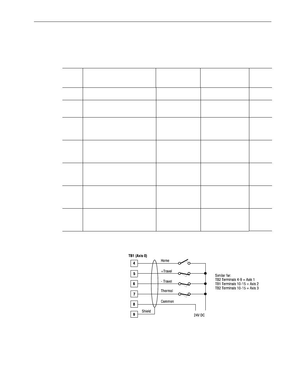
The following tables provide descriptions of the various control
signals shown in Figure 4.1. Terminate the signals you need for your
application using the terminal operating tool.
Figure 4.4
Home, Travel and Thermal Fault Inputs
Wire:
Description:
Terminal connections for
1394
x-SJTxx-C, -C-RL
and -T, -T-RL systems:
Terminal connections for
1394C-SJT
xx-L and
-L-RL systems:
Mandatory
or Optional:
SYS
ENABLE
A 24V DC input is applied to these terminals
to enable the system.
Either TB1 or TB2,
terminal 1
Either TB1 or TB2,
terminal 1
Mandatory
24V
INPUT
COM
Common grounding point for 24V signals.
TB1 and TB2 terminals 2,
8, and 14
TB1 terminals 2 and 8
Mandatory
CHASSIS
Common chassis ground point.
TB1 terminals 3, 9, 15,
19, 23, and 27
TB2 terminals 3, 9, 15,
19, 23, 26, and 27
TB1 terminals 3,9,19 and 27
TB2 terminals 3,19,26 and 27
Mandatory
HOME0
Home switch inputs for each axis require
24V DC (each), 13 mA to energize. Each
input is optically isolated and filtered to
minimize switch bounce. Refer to Figure 4.4.
TB1 - 4 (axis 0),
TB2 - 4 (axis 1),
TB1 - 10 (axis 2),
TB2 - 10 (axis 3)
TB1 - 4 (axis 0)
Optional
POS
OTRAV0
The positive limit switch inputs for each axis
require 24V DC (each), 13 mA to energize.
Each input is optically isolated and filtered to
minimize switch bounce. Refer to Figure 4.4.
TB1 - 5 (axis 0),
TB2 - 5 (axis 1),
TB1 - 11 (axis 2),
TB2 - 11 (axis 3)
TB1 - 5 (axis 0)
Optional
NEG
OTRAV0
The negative limit switch inputs for each axis
require 24V DC (each), 12 mA to energize.
Each input is optically isolated and filtered to
minimize switch bounce. Refer to Figure 4.4.
TB1 - 6 (axis 0),
TB2 - 6 (axis 1),
TB1 - 12 (axis 2),
TB2 - 12 (axis 3)
TB1 - 6 (axis 0)
Optional
THERM
FLT0
The thermal fault switch inputs for each axis
require 24V DC (each), 12 mA to energize.
Each input is optically isolated and filtered to
minimize switch bounce. Refer to Figure 4.4.
TB1 - 7 (axis 0),
TB2 - 7 (axis1),
TB1 - 13 (axis 2),
TB2 - 13 (axis 3)
TB1 - 7 (axis 0)
Optional