Shunt module mounting orientation – Rockwell Automation 1326 Digital AC Multi-Axis Motion Control System User Manual User Manual
Page 42
Publication 1394-5.0 — May 2000
2-12
Installing Your 1394 (applies to all systems)
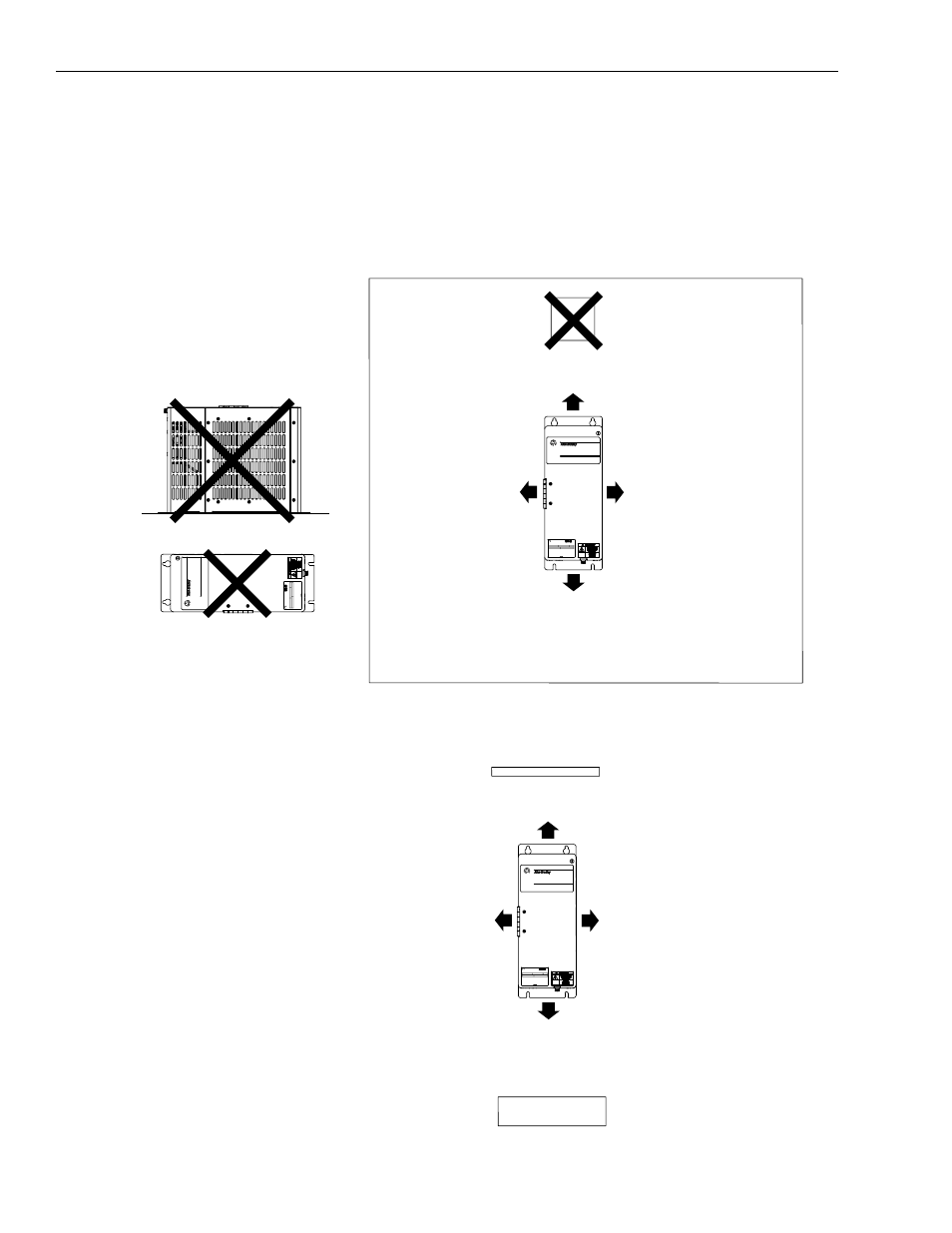
Shunt Module Mounting Orientation
Because the shunt module dissipates excess regenerative power in the
form of heat, you need to consider the following guidelines. Refer to
Figure 2.11 and Figure 2.12 for shunt module spacing requirements.
Figure 2.11
Shunt Module Spacing Requirements Within an Enclosure
Figure 2.12
Shunt Module Spacing Requirements Outside of an Enclosure
254 mm (10.0 in.) clearance
for airflow and installation
155 mm (6.1 in.) clearance
for airflow and installation
155 mm (6.1 in.) clearance
for airflow and installation
155 mm (6.1 in.) clearance
for airflow and installation
Wire entry area
for signal, power and motor connections
Top of cabinet
Temperature sensitive component
(mounted above shunt module)
Incorrect Shunt Placement
1394 Digital Servo Controller
3600W Shunt Module
BULLETIN 1394 3600W SHUNT MODULE
ALLEN-BRADLEY
FOR USE WITH 1394-SJT22-X SYSTEM MODULE
CAT.
PART
SER.
INPUT DC
INPUT AC
FOR FUSE REPLACEMENT USE:
BUSSMAN CAT. NO.
R
1394 Digital Servo Controller
3600W Shunt Module
BULLETIN 1394 3600W SHUNT MODULE
ALLEN-BRADLEY
FOR USE WITH 1394-SJT22-X SYSTEM MODULE
CAT.
PART
SER.
INPUT DC
INPUT AC
FOR FUSE REPLACEMENT USE:
BUSSMAN CAT. NO.
R
Enclosure
254 mm (10.0 in.) clearance
for airflow and installation
155 mm (6.1 in.) clearance
for airflow and installation
155 mm (6.1 in.) clearance
for airflow and installation
155 mm (6.1 in.) clearance
for airflow and installation
Wire entry area
for signal, power and motor connections
Solid protective plate
1394 Digital Servo Controller
3600W Shunt Module
BULLETIN 1394 3600W SHUNT MODULE
ALLEN-BRADLEY
FOR USE WITH 1394-SJT22-X SYSTEM MODULE
CAT.
PART
SER.
INPUT DC
INPUT AC
FOR FUSE REPLACEMENT USE:
BUSSMAN CAT. NO.
R