Rockwell Automation 1326 Digital AC Multi-Axis Motion Control System User Manual User Manual
Page 256
Publication 1394-5.0 — May 2000
B-24
Interconnect and CE Diagrams
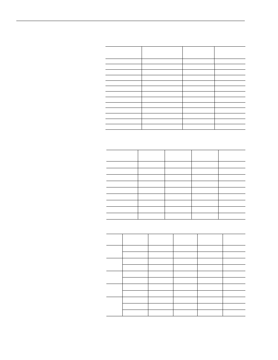
1326-CECUx-xxx L-xxx High-Resolution Feedback Cable Wiring
Information for High-Resolution Servo Motors Only
1326-CPB1-xxx Standard Motor Power Cable for 1326AS-
B3xxxx, 1326-AB/AS-B4xxxx and 1326AB-B5xxxx Servo Motors
1326-CEU-xxx Encoder Feedback Cable
Wire Number
Wire Color
Gauge
mm
2
(AWG)
System Module
Terminal #
A
Black (power)
0.519 (20)
3
B
White (ground)
0.519 (20)
2
no connection
Shield
0.519 (20)
no connection
C
Black (ChA_LO)
0.519 (20)
11
D
Red (ChA_HI)
0.519 (20)
12
I
Shield
0.519 (20)
10
E
Black (ChB_LO)
0.519 (20)
8
F
Blue (ChB_HI)
0.519 (20)
9
I
Shield
0.519 (20)
7
G
Black (Comm_HI)
0.519 (20)
6
H
Green (Comm_LO)
0.519 (20)
5
I
Shield
0.519 (20)
4
J
Overall Shield
N/A
1
Wire Number
Wire Color
Gauge
mm
2
(AWG)
Connector
Pin
1394
Terminal
1 (Power)
Black
1.3 (16)
1
U1
2 (Power)
Black
1.3 (16)
2
V1
3 (Power)
Black
1.3 (16)
3
W1
4 (Brake)
Black
1.3 (16)
4
TB1-3
5 (Thermostat)
Black
1.3 (16)
5
TB1-2
6 (Brake)
Black
1.3 (16)
6
TB1-4
Braided shield
Braided shield
N/A
7
PE3
(GND)
Green/Yellow
1.3 (16)
8
PE2
9 (Thermostat)
Black
1.3 (16)
9
TB1-1
Pair #
Wire Color
Gauge
mm
2
(AWG)
Connector
Pin
Description
1394
Terminal
1
Black
0.34 (22)
H
A (NOT)
2
White
0.34 (22)
A
A
1
2
Black
0.34 (22)
F
Common
9
Red
0.34 (22)
D
+5V
8
3
Black
0.34 (22)
J
Z (NOT)
6
Orange
0.34 (22)
C
Z
5
4
Black
0.34 (22)
I
B (NOT)
4
Blue
0.34 (22)
B
B
3
5
Black
0.34 (22)
F
Common
9
Green
0.34 (22)
E
no connection
Braided Shield N/A
G
Shield