Rockwell Automation 1326 Digital AC Multi-Axis Motion Control System User Manual User Manual
Page 57
Publication 1394-5.0 — May 2000
Wiring System, Axis, and Shunt Modules, and Motors (for all systems)
3-11
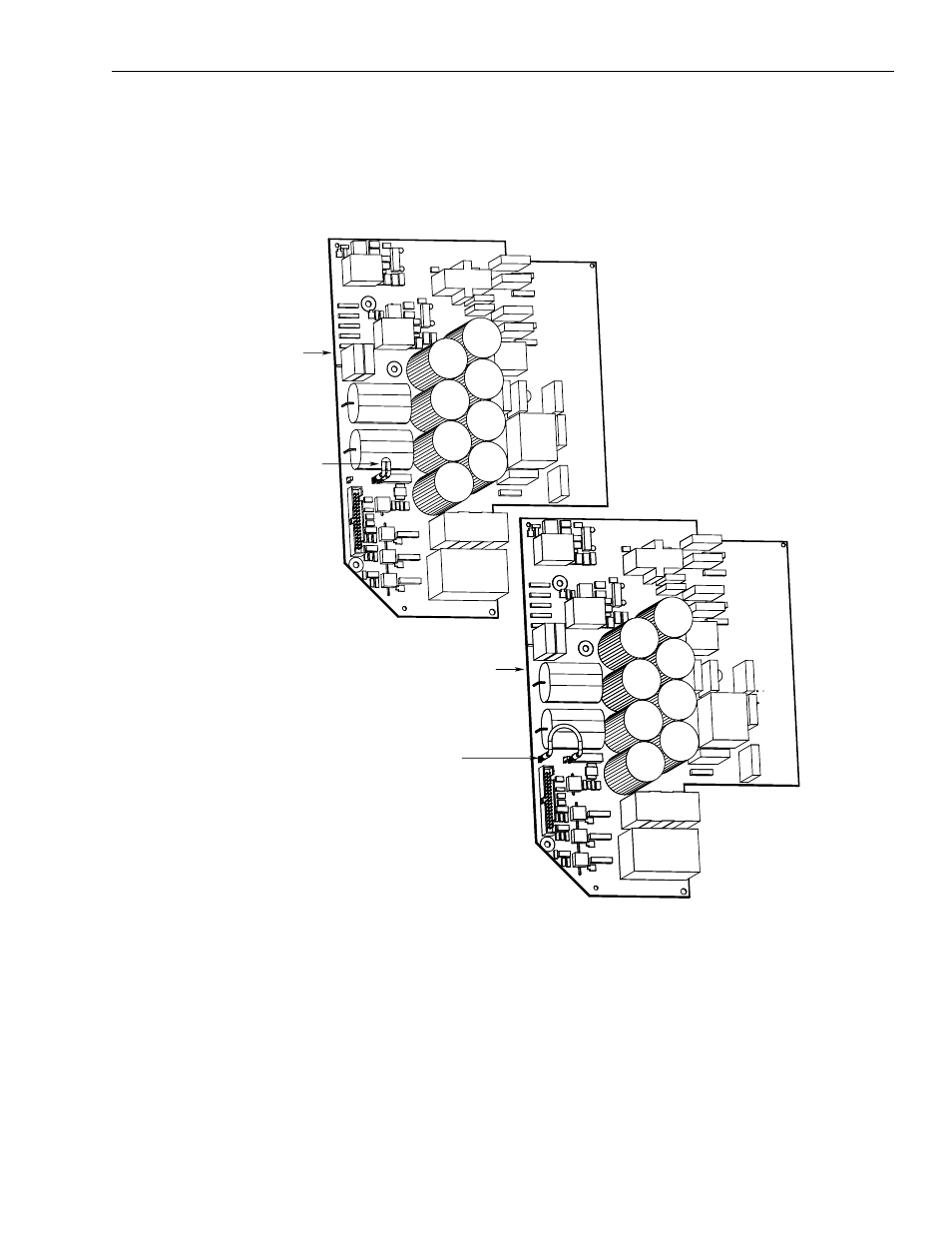
7. Without removing the circuit board, unplug the jumper and move
it to the ungrounded power distribution position. Refer to the
figure below for the jumper positions.
Figure 3.7
22 kW System Module Jumper Positions
8. Re-install the input wiring board.
9. Re-install the upper and lower input wiring board screws. Refer
to Figure 3.5 for the location of the screws.
10. Re-connect both ends of the input wiring board ribbon cable.
Refer to Figure 3.5 for the location of the ribbon cable.
11. Close the system module door.
12. Go to Grounding Your 1394 System.
Factory default jumper
position for a grounded
configuration
Jumper position for an
ungrounded power
configuration
Front edge
of board
Front edge
of board
DO NOT REMOVE CIRCUIT
BOARD FROM 1394