Rockwell Automation 1326 Digital AC Multi-Axis Motion Control System User Manual User Manual
Page 71
Publication 1394-5.0 — May 2000
Wiring System, Axis, and Shunt Modules, and Motors (for all systems)
3-25
To improve the bond between the motor feedback cable shield and the
system module PE ground, a cable shield clamp is included with the
Series C system modules.
Ensure an appropriate amount of the cable insulation and braided
shield is removed from the feedback cable. Place the cable wires and
exposed braided shield into the cable shield clamp and tighten the
clamp screw. Then thread the bracket screw into the bottom of the
system module and tighten. Refer to Figure 3.14 for an illustration.
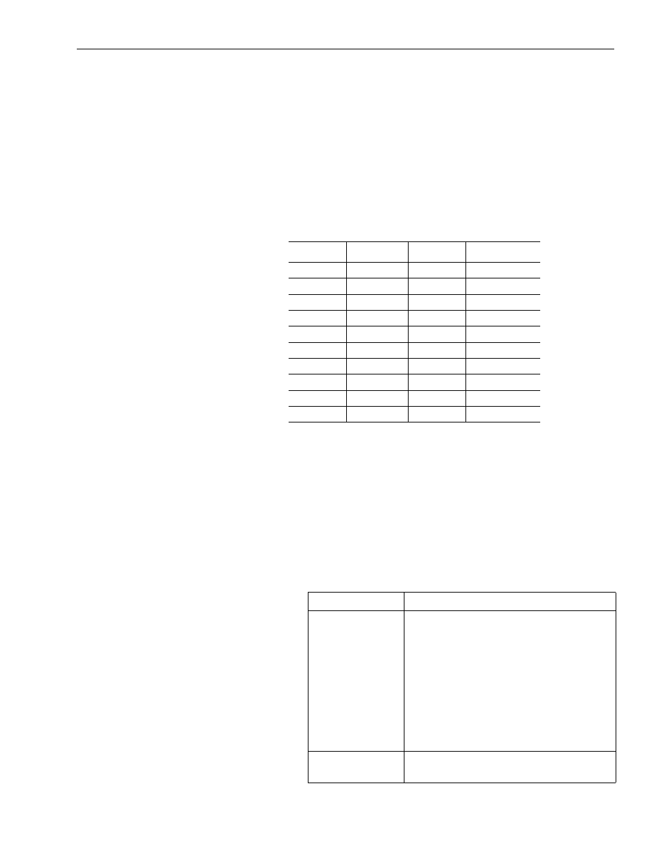
The table below provides pin-outs for the resolver connection.
To connect motor feedback:
1. Connect the connector shells to the resolver feedback cables.
2. For each axis/motor you will use, connect one motor resolver
feedback cable to the appropriate feedback connector on the
bottom of the system module control board. For the location of
those connectors, refer to the drawing on the inside of the system
module door or the section Finding Additional Wiring
Information for 1394 Systems.
3.
Terminal:
Wire Number:
Color:
Function:
1
1
Black
Axis x R1
2
1
Shield
Shield
3
2
Black
Axis x S1
4
3
Green
Axis x S2
5
3
Shield
Shield
6
1
White
Axis x R2
7
2
Shield
Shield
8
2
Red
Axis x S3
9
3
Black
Axis x S4
10
Overall Shield
Overall Shield
Overall Shield
If you are:
Do this:
Using the AQuadB
option (for Analog
Servo system
only)
1. Connect the connector shells to the 1394-
SA15 cables. Refer to the instructions
that came with the cables for more
information.
2. For each AQuadB output you will use,
connect one 1394-SA15 cable to the
AQuadB mating slot under the system
module.
3. Go to step 4.
Not using the
AQuadB option
Go to step 4.