Cable pin-outs, 1326 cable pin-outs – Rockwell Automation 1326 Digital AC Multi-Axis Motion Control System User Manual User Manual
Page 255
Publication 1394-5.0 — May 2000
Interconnect and CE Diagrams
B-23
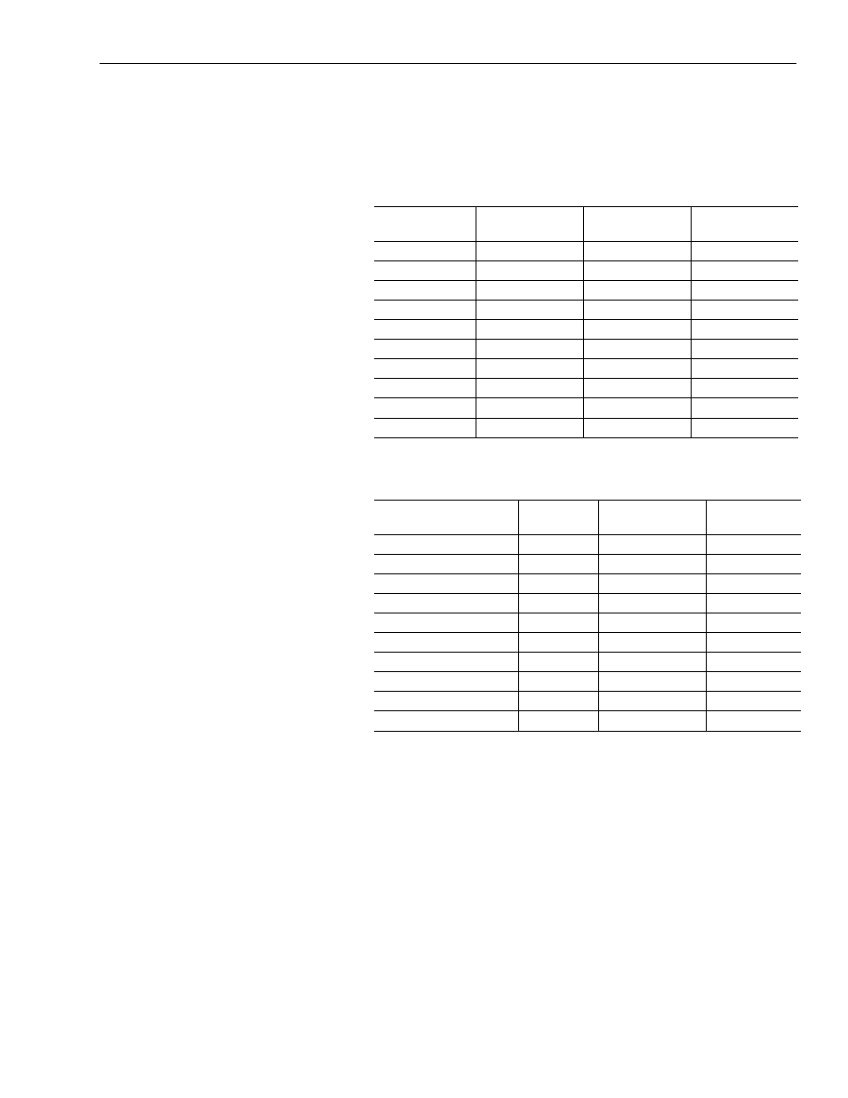
Cable Pin-outs
1326 Cable Pin-outs
Pin-outs and interconnect information for the 1326 interconnect
cables are provided starting below.
1326-CCU-xxx Standard Commutation Cable for Motor Resolver
1326-CCUT-xxx Flex Rated Commutation Cable for Motor
Resolver
Wire Color
Gauge
mm
2
(AWG)
Connector Pin
System Module
Terminal #
Black (Axis_0_R1)
0.519 (20)
A
1
White (Axis_0_R2)
0.519 (20)
B
6
Shield - Drain
0.519 (20)
no connection
2
Black (Axis_0_S1)
0.519 (20)
D
3
Red (Axis_0_S3)
0.519 (20)
E
8
Shield - Drain
0.519 (20)
no connection
7
Black (Axis_0_S4)
0.519 (20)
H
9
Green (Axis_0_S2)
0.519 (20)
G
4
Shield - Drain
0.519 (20)
no connection
5
Overall Shield
N/A
no connection
10
Wire Color
Gauge
mm
2
(AWG)
Connector Pin
System Module
Terminal #
White/Black (Axis_0_R1)
0.519 (20)
A
1
White (Axis_0_R2)
0.519 (20)
B
6
Shield
0.519 (20)
no connection
2
White/Black (Axis_0_S1)
0.519 (20)
D
3
White/Red (Axis_0_S3)
0.519 (20)
E
8
Shield
0.519 (20)
no connection
7
White/Black (Axis_0_S4)
0.519 (20)
H
9
White/Green (Axis_0_S2)
0.519 (20)
G
4
Shield
0.519 (20)
no connection
5
Green/Yellow
N/A
no connection
10