Figure 3.4, In step 4, Figure 3.4 for – Rockwell Automation 1326 Digital AC Multi-Axis Motion Control System User Manual User Manual
Page 55
Publication 1394-5.0 — May 2000
Wiring System, Axis, and Shunt Modules, and Motors (for all systems)
3-9
4. Close the system module door.
5. Go to Grounding Your 1394 System.
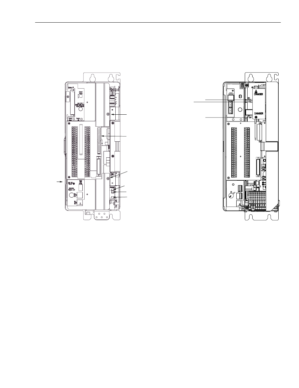
Figure 3.4
Ground Jumper Locations for the 5 and 10 kW System Modules
Setting the Ground Jumper in a 22 kW System Module for
Ungrounded Power Configurations
This procedure assumes that you have bonded and mounted your
1394x-SJT22-x system module to the subpanel and that there is no
power applied to the system. To set the ground jumper:
Important: If you have grounded power distribution, you do not
need to set the ground jumper. Go to Grounding Your
1394 System.
1. Verify that all 24V control and 360/480V power has been
removed from the system.
2. Open the system module door.
3. Disconnect both ends of the input wiring board ribbon cable.
Refer to Figure 3.5 for the location of the ribbon cable.
4. Remove the upper and lower input wiring board screws. Refer to
Figure 3.5 for the location of the screws.
5. Remove the input wiring board.
1394C-SJT
xx-x
(5 and 10 kW Series C)
Upper
Control Board
Screw
J4
J5
J6
Ribbon
Cable
Connector
Side
Control Board
Screw
Lower
Control Board
Screw
J27
J26
GND3
1394-SJT
xx-x
(5 and 10 kW Series A and B)