Rockwell Automation 1326 Digital AC Multi-Axis Motion Control System User Manual User Manual
Page 35
Publication 1394-5.0 — May 2000
Installing Your 1394 (applies to all systems)
2-5
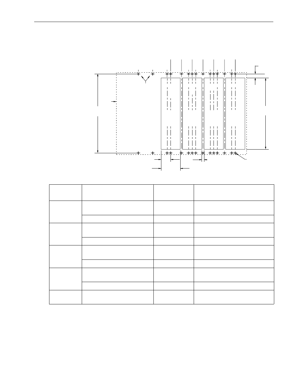
Figure 2.2
1394 Mounting Hole Layout
2. Once you have identified your axis module combination, modify
your subpanel using the dimensions that correspond with the
combination you chose in step one.
3. Go to Bonding Your System.
Axis Module
Combination
Type of Axis Module
Number of Axes Cutout Needed?
A
1394x-AM50, or -AM75, and
1394C-AM50-IH, or -AM75-IH
0
no
1394x-AM03, AM04, or AM07
up to 4
no
B
1394x-AM50, or -AM75, and
1394C-AM50-IH, or -AM75-IH
1
yes (1394x-AM50 or -AM75)
no (1394C-AM50-IH or -AM75-IH)
1394x-AM03, AM04, or AM07
up to 3
no
C
1394x-AM50, or -AM75, and
1394C-AM50-IH, or -AM75-IH
2
yes (1394x-AM50 or -AM75)
no (1394C-AM50-IH or -AM75-IH)
1394x-AM03, AM04, or AM07
up to 2
no
D
1394x-AM50, or -AM75, and
1394C-AM50-IH, or -AM75-IH
3
yes (1394x-AM50 or -AM75)
no (1394C-AM50-IH or -AM75-IH)
1394x-AM03, AM04, or AM07
up to 1
no
E
1394x-AM50, or -AM75, and
1394C-AM50-IH, or -AM75-IH
4
yes (1394x-AM50 or -AM75)
no (1394C-AM50-IH or -AM75-IH)
Note: When mounting axis module combinations, you must mount the 1394x-AM50, -AM75, -AM50-IH, and -AM75-IH closest to the system
module and ahead of the 1394x-AM03, -AM04, and -AM07 axis modules.
50
(1.97)
0
(0.00)
62.5
(2.46)
50
(1.97)
125
(4.92)
100
(3.94)
137.5
(5.41)
175
(6.89)
200
(7.87)
212.5
(8.37)
225
(8.86)
250
(9.84)
275
(10.83)
287.5
(11.32)
System module
mounting holes
Heat sink
cutout for the
AM50/75
module
only
Heat sink
cutout for the
AM50/75
module
only
Heat sink
cutout for the
AM50/75
module
only
Heat sink
cutout for the
AM50/75
module
only
B
C
D
E
B
B
B C
D
E
A
C
C
D
E
D E
19.5
(0.768)
33.5 TYP
(1.32)
67 TYP
(2.64)
8 TYP
(0.32)
M6 tapped hole or
1/4-20 UNC - 2B
385
(15.16)
348
(13.70)
Dimensions are in millimeters and (inches)
System
outline
A
A
A
150
(5.91)