System modules – Rockwell Automation 1326 Digital AC Multi-Axis Motion Control System User Manual User Manual
Page 200
Publication 1394-5.0 — May 2000
A-2
Specifications
System Modules
The table below lists the specifications for system modules.
The:
For the 1394
x-SJT05
1,2
is:
For the 1394
x-SJT10
1,2
is:
For the 1394
x-SJT22
1
is:
Rated AC input voltage
324-528V AC, 50/60 Hz
Three phase
324-528V AC, 50/60 Hz
Three phase
324-528V AC, 50/60 Hz
Three phase
AC input current
6.5A
13.0A
28.6A
Peak inrush current
4,5
(Series A and B)
3
975A
1300A
697A < 1
µ
s
Peak inrush current
4
(Series C)
697A < 1
µ
s
697A < 1
µ
s
697A < 1
µ
s
Line loss ride through
20 ms
20 ms
20 ms
Nominal bus output voltage
530/680V DC
530/680V DC
530/680V DC
Continuous power output
4/5 kW
8/10 kW
17/22 kW
Peak power output
28 kW
28 kW
136 kW
Efficiency
99%
99%
98%
Number of Electronic Cam
Profile Points
13,000 Master/slave
13,000 Master/slave
13,000 Master/slave
Weight (Series A and B)
11 kg (24.25 lb)
11 kg (24.25 lb)
12.7 kg (28.0 lb)
Weight (Series C)
10.68 kg (23.5 lb)
10.68 kg (23.5 lb)
12.9 kg (28.5 lb)
Continuous current output
7.36A
14.73A
33.8A
Peak current output
15.0A
29.46A
200A
Capacitance
(Series A and B)
220
µ
F
330
µ
F
660
µ
F
Capacitance
(Series C)
220
µ
F
345
µ
F
660
µ
F
Inductance
1000
µ
H
750
µ
H
500
µ
H
Internal shunt resistor
200W continuous, 40,000W peak (two second maximum on
time)
No internal Shunt Resistor
1
The Standard GMC and GMC Turbo system modules are identical except that the GMC Turbo (1394
x-SJTxx-T) offers a SLC backplane
interface and 64K of memory with a 32-bit processor while the Standard GMC (1394
x-SJTxx-C) offers 32K of program memory with a 16-
bit processor without the SLC interface.
2
The Standard GMC (1394C-SJT
xx-L) is functionally the same as the (1394x-SJTxx-C) except it supports one axis and provides two auxiliary
encoder inputs.
3
To determine the series of your module, refer to Figure P.1 in the
Preface.
4
5 and 10 kW (Series C) system modules and all 22 kW system modules are limited to four contactor cycles per minute. 5 and 10 kW (Series
A and B) system modules are limited to an average of four contactor cycles per hour.
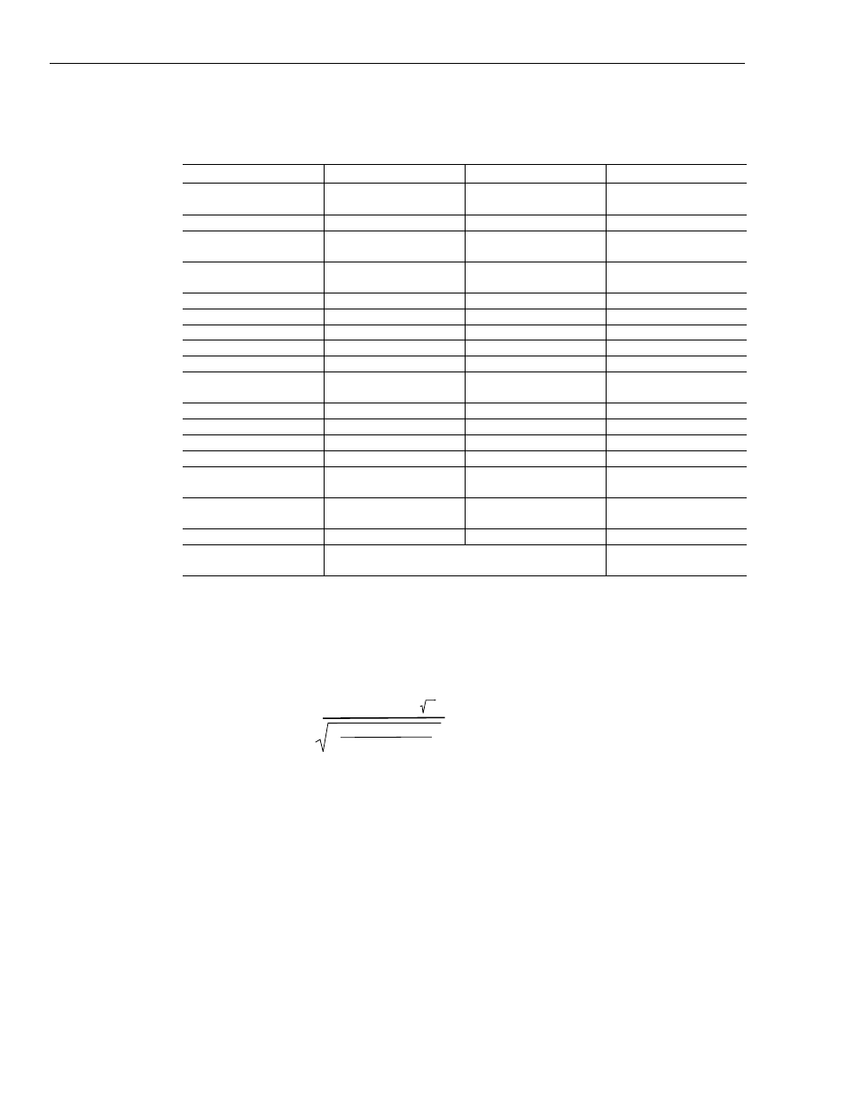
Peak inrush current for
5 and 10 kW systems
(Series A and B)
5
=
( line voltage x 1.1 x 2 )
Lsystem
(
)
(Csystem + Caxes)
Where: L = Inductance
C = Capacitance