Rockwell Automation 1326 Digital AC Multi-Axis Motion Control System User Manual User Manual
Page 116
Publication 1394-5.0 — May 2000
5-6
Wiring Your 1394 Analog Servo System
Make the A Quad B connections at the bottom of the system module
(refer to Figure 5.3) as follows:
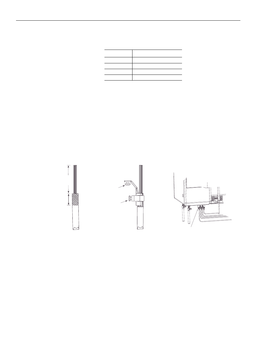
To improve the bond between the motor feedback cable shield and the
system module PE ground, a cable shield clamp is included with the
Series C system modules.
Ensure an appropriate amount of the cable insulation and braided
shield is removed from the feedback cable. Place the cable wires and
exposed braided shield into the cable shield clamp and tighten the
clamp screw. Then thread the bracket screw into the bottom of the
system module and tighten. Refer to the figure below for an
illustration.
Figure 5.4
Series C System Module Cable Clamp
For this axis:
Connect to this terminal:
0
AQB0
1
AQB1
2
AQB2
3
AQB3
1394 front view
System module
ground bar
Feedback
cable clamps
Cable Preparation
Clamp Attachment
Wiring to System Module
Cable wires
Braided
shield
exposed
Cable
shield
clamp
Motor
cable
Clamp
screw
Bracket
screw
51 mm
(2.0 in.)
1
22 mm
(.875 in.)
1
Dimensions given are approximate and will vary
depending on the specific installation. Keep wires
as short as possible while maintaining adequate
stress relief.
1