Rockwell Automation 1326 Digital AC Multi-Axis Motion Control System User Manual User Manual
Page 77
Publication 1394-5.0 — May 2000
Wiring System, Axis, and Shunt Modules, and Motors (for all systems)
3-31
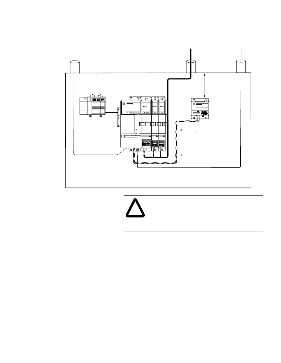
Figure 3.19
Routing Shunt Module Wiring When Module is Inside the Cabinet
7. Open the front door of the shunt module.
8. Insert the wire from the system module terminal block labeled
COL in the top terminal on the left side of the shunt module.
Refer to Figure 3.20 for the terminal’s location.
9. Insert the wire from the system module terminal block labeled
DC+ in the bottom terminal on the left side of the shunt module.
Refer to Figure 3.20 for the terminal’s location.
!
ATTENTION: To avoid burn hazard and ignition of
flammable material, be sure to provide appropriate
guarding. The resistors inside the 1394 shunt module
can reach temperatures in excess of 350
°
C (662
°
F).
Install per local codes.
Status
Low voltage
Communications
Control I/O wiring
Motor feedback cables
360/480V
AC power
Always separate all low voltage signal
wiring from high voltage power wiring to
reduce affects of EMI and RFI.
Motor power
cables
155 mm (6.1 in.) of
clearance on all sides
of the shunt module
minimum
Use twisted conductors
(2 twists per foot) min. or
a shielded twisted pair.
8 AWG (8.4 mm
2
),
105 C, 600V wire
Max. Length 3.05 m
(10 ft) for each wire
1394 Digital Servo Controller
300W Shunt Module
BULLETIN 1394 300W SHUNT MODULE
ALLEN-BRADLEY
FOR USE WITH 1394-SJT22-X SYSTEM MODULE
CAT.
PART
SER.
INPUT DC
INPUT AC
FOR FUSE REPLACEMENT USE:
BUSSMAN CAT. NO.
R
Shielding is recommended
for reducing the effects
of EMI and RFI.
DANGER
RISK OF ELECTRICAL SHOCK. HIGH VOLTAGE MAY
EXIST UP TO FIVE MINUTES AFTER REMOVING POWER.