Determining your system mounting hole layout – Rockwell Automation 1326 Digital AC Multi-Axis Motion Control System User Manual User Manual
Page 34
Publication 1394-5.0 — May 2000
2-4
Installing Your 1394 (applies to all systems)
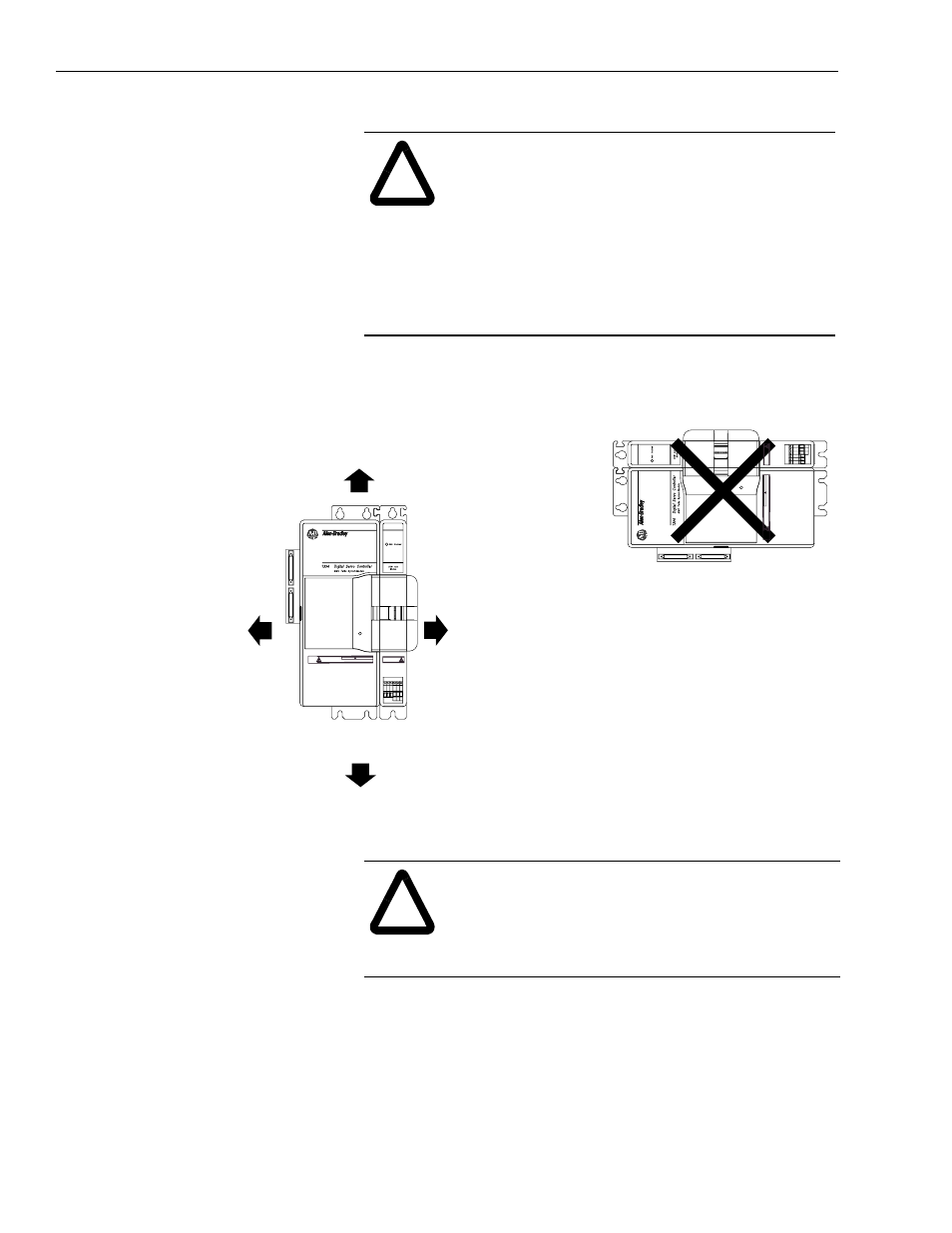
Figure 2.1
Minimum System and Axis Module Mounting Requirements
Determining Your System Mounting Hole Layout
To prepare your subpanel for mounting:
1. Before you mount your 1394 System, use the illustration and
table on the next page to identify your axis module combination.
!
ATTENTION: This drive contains ESD (Electrostatic
Discharge) sensitive parts and assemblies. You are
required to follow static control precautions when you
install, test, service, or repair this assembly. If you do
not follow ESD control procedures, components can be
damaged. If you are not familiar with static control
procedures, refer to Allen-Bradley publication 8000-
4.5.2, Guarding Against Electrostatic Damage or any
other applicable ESD Protection Handbook.
!
ATTENTION: If you are mounting a 1394x-SJTxx-
T system module, and using the SLC Interface, you
will need an additional 101.6 mm (4 in.) of clearance
to the left of the system module to allow for connecting
the SLC interface cable (1746-C7 or -C9).
Allow 50.8 mm (2.00 in.) clearance
for airflow and installation.
Allow additional clearance below the system module to provide the recommended cable bend radius.
Refer to
1326 Cables for 460V AC Servo Motors (publication 1326A-2.11) for more information.
Allow 10.0 mm (0.4 in.) side clearance.
Allow 25.4 mm (1.00 in.) clearance
at cover tab for opening and closing.
(See ATTENTION: statement below)
Allow 10.0 mm (0.4 in.) side clearance.
Allow 76.2 mm (3.00 in.) clearance
for depth of terminator.
Status
Status
DANGER
RISK OF ELECTRICAL SHOCK. HIGH VOLTAGE MAY
EXIST UP TO FIVE MINUTES AFTER REMOVING POWER.
D
ANGER
RISK OF ELECTRICAL SHOCK.
HIGH
VOL
TAGE MA
Y
EXIST UP
TO FIVE MINUTES
AFTER REMOVING POWER.
Wire entry area for cable ground clamps and
signal, power, and motor connections.