8 configuration – in setup program only – JUMO 705010 mTRON T - Multichannel Controller Module Operating Manual User Manual
Page 122
8 Configuration – in setup program only
122
Measured value
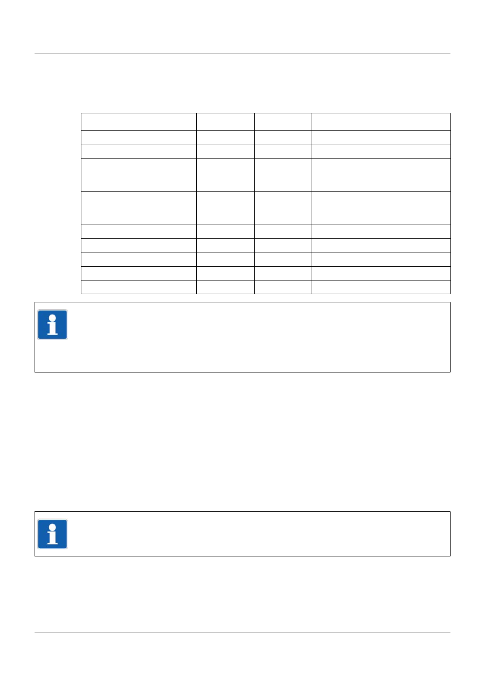
The table below shows the admissable measured value range of the analog inputs, depending
on the chosen sensor (incl. physical offset, if applicable). These values are the minimum and
the maximum input values for the customer-specific linearization.
Linearization
Depending on the type of linearization, either the domain or the co-domain of the linearization
is monitored.
Chapter 8.1.1 "Grid points", page 123
Chapter 8.1.2 "Formula", page 124
Linearized value
The linearized value is monitored with respect to the scale range (start, end). As a result, the
range of linearized values (incl. standardized offset, if applicable) is limited as follows:
Lower limit = minimum(start, end) - |end - start| × 0.0125
Upper limit = maximum(start, end) + |end - start| × 0.03125
Sensor
Lower limit
Upper limit
Comment
RTD temperature probe
0
4000
Thermocouple
0 mV
100 mV
Resistance transmitter
0 %
100 %
Sliding contact position, as a per-
centage of the overall resistance
(max. 4000
)
Resistance/potentiometer
0 %
100 %
Sliding contact position, as a per-
centage of the overall resistance
(max. 4000
)
Current 0 to 20 mA
0 mA
20.625 mA
Underrange is not detected.
Current 4 to 20 mA
3.8 mA
20.5 mA
Voltage 0 to 1 V
-0.0125 V
1.03125 V
Voltage 0 to 10 V
-0.125 V
10.3125 V
Voltage 2 to 10 V
1.9 V
10.25 V
TIP!
In the case of standard signals (current, voltage), the measured value is monitored (incl. phy-
sical offset, if applicable). The current and voltage values that are specified in the table repre-
sent the limits acc. to NAMUR recommendation NE 43 (exception: lower limit for current
0 to 20 mA). A measured value beyond these limits causes an overange or an underrange
(out-of-range).
TIP!
A linearized value beyond these limits causes an overange or an underrange (out-of-range).