JUMO 705001 mTRON T - Central Processing Unit Data Sheet User Manual
Central processing unit, Brief description, Block diagram
JUMO GmbH & Co. KG
Delivery address: Mackenrodtstraße 14
36039 Fulda, Germany
Postal address:
36035 Fulda, Germany
Phone:
+49 661 6003-0
Fax:
+49 661 6003-607
E-mail:
Internet:
www.jumo.net
JUMO Instrument Co. Ltd.
JUMO House
Temple Bank, Riverway
Harlow, Essex CM20 2DY, UK
Phone: +44 1279 635533
Fax:
+44 1279 635262
E-mail:
Internet: www.jumo.co.uk
JUMO Process Control, Inc.
6733 Myers Road
East Syracuse, NY 13057, USA
Phone: 315-437-5866
1-800-554-5866
Fax:
315-437-5860
E-mail:
Internet: www.jumousa.com
Page 1/10
JUMO mTRON T
Measuring, Control, and Automation System
Central processing unit
Brief description
The central processing unit is the heart of the system. It contains the
process image of the application and manages the configuration and
parameter data of the complete system (except for the multifunction
panel).
For individual control tasks nine program generators (option) are avail-
able and 64 limit values can be monitored.
LEDs are used to indicate applied voltage supply, the operating status
of the PLC, system malfunctions, as well as the communication through
interfaces.
A USB device interface (setup), a LAN connection (Ethernet), and two
system bus connections are available as standard. Up to two interfaces
can be optionally equipped for fieldbus applications.
The central processing unit, the input/output modules connected later-
ally, and modules integrated by a router are comfortably configured and
parameterized with the setup program.
A PLC according to IEC 61131-3 can be released as an option. A switch
is available to toggle the system operating status (Run, Stop, and Re-
set).
Type 705001/...
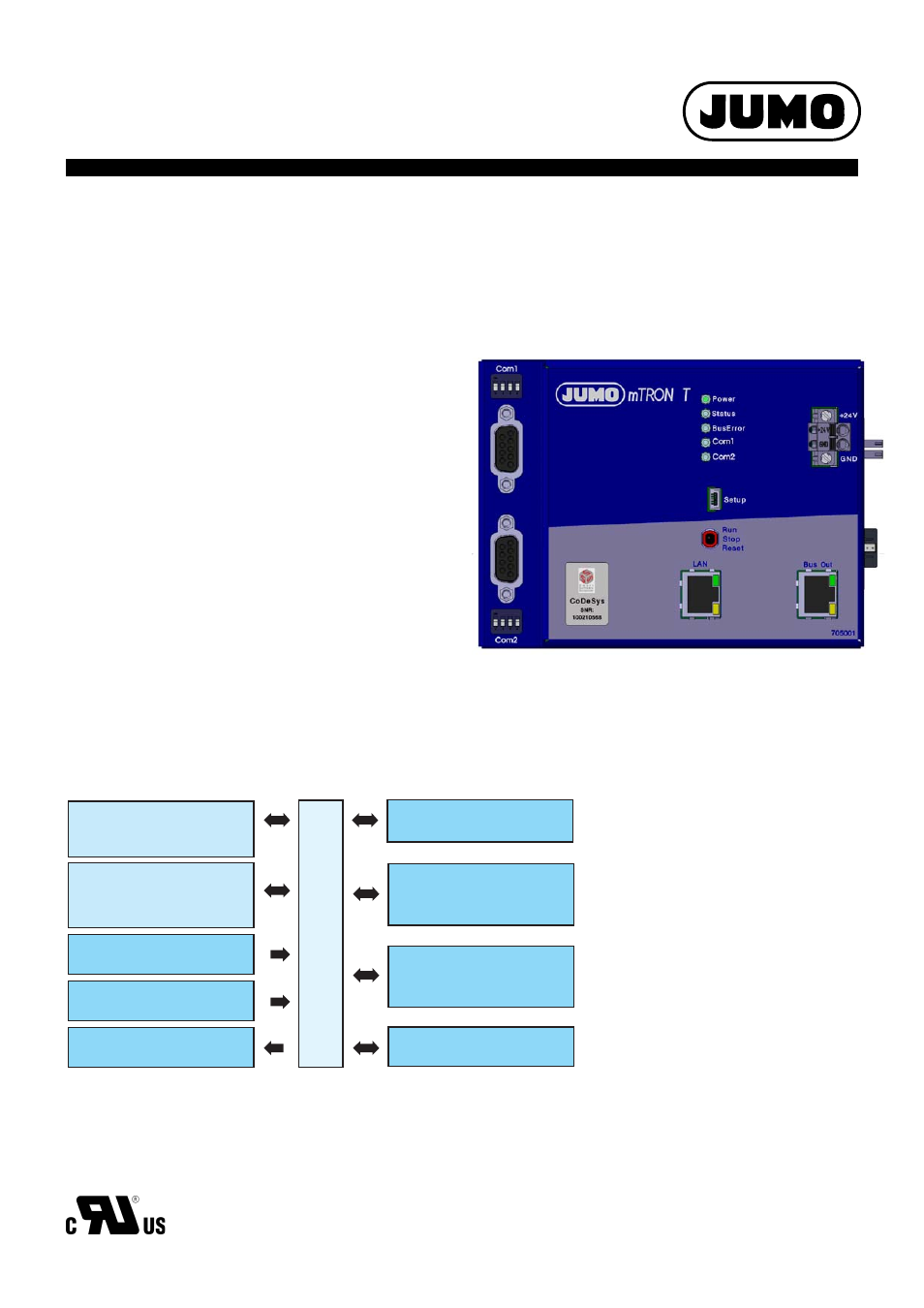
Block diagram
Com1
RS232 (Modbus RTU) or
RS422/485 (Modbus RTU)
705001
Voltage supply Out
System bus
Com2
RS232 (Modbus RTU) or
RS422/485 (Modbus RTU) or
PROFIBUS-DP slave
USB (device)
For setup program
Bus Out
To permit connection to a
multifunction panel or
router module
LAN
Mainly for use of the
integrated web server
or the setup program
Switch / push-button
Run, Stop, or Reset
Voltage supply In
(at the front)
Features
• Process image for up to 30 input/output
modules
• Ethernet interface with integrated
web server
• One USB interface
• 64 limit values can be monitored
• PLC acc. to IEC 61131-3 (option)
• OPC server (in connection with PLC)
• Nine program generators (option)
• Two field bus interfaces (option)
• Math and logic module (option, activation
for all connected controller modules)
• System bus connection on the front (Bus
Out)
• Plug and Play when replacing the input/out-
put modules
• Battery buffered RAM
• Real time clock
• Sturdy metal case
• Supply of operating voltage
• Quick wiring of operating voltage and sys-
tem bus due to easy module connection
Approval/approval marks (see “Technical data”)
Data Sheet 705001
2014-08-22/00529105