JUMO 705060 mTRON T - Multifunction Panel 840 Data Sheet User Manual
Multifunction panel 840, Brief description, Block diagram
Page 1/13
JUMO GmbH & Co. KG
Delivery address: Mackenrodtstraße 14
36039 Fulda, Germany
Postal address:
36035 Fulda, Germany
Phone:
+49 661 6003-0
Fax:
+49 661 6003-607
E-mail:
Internet:
www.jumo.net
JUMO Instrument Co. Ltd.
JUMO House
Temple Bank, Riverway
Harlow, Essex CM20 2DY, UK
Phone: +44 1279 635533
Fax:
+44 1279 635262
E-mail:
Internet: www.jumo.co.uk
JUMO Process Control, Inc.
6733 Myers Road
East Syracuse, NY 13057, USA
Phone: 315-437-5866
1-800-554-5866
Fax:
315-437-5860
E-mail:
Internet: www.jumousa.com
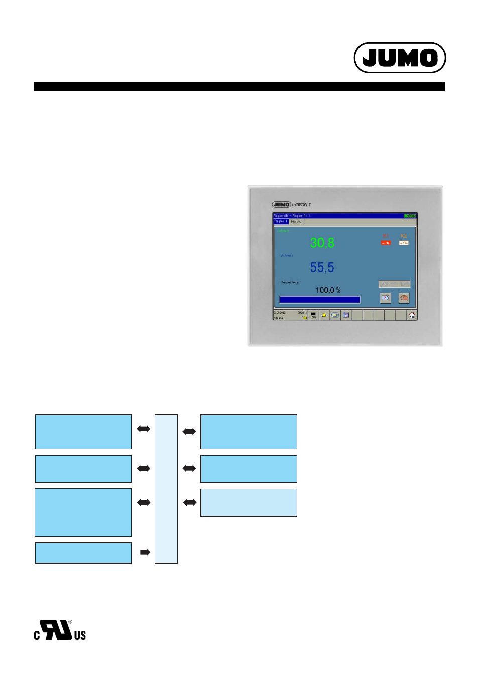
JUMO mTRON T
Measuring, Control, and Automation System
Multifunction panel 840
Brief description
The multifunction panel 840 with TFT-touchscreen allows easy and
clearly-arranged measured data visualization, operation, configuration,
and parameterization of the system.
The TFT color screen has a screen size of 21.3 cm (8.4“), a resolution
of 640 × 480 pixels, 256 colors, and LED backlight.
As the interface between man and machine, the panel allows an opti-
mum and clearly-arranged view of the process status and the system
parameters. In addition, it is perfectly suitable for the display and
operation of controller screens, process screens, the program editor,
and the optional recording function. Setpoint values, batch text, param-
eters, and configuration data can be directly entered and changed by
the user on the screen.
The process data that is transmitted by the system bus is shown in real
time. Data archiving and evaluation is made possible by established
PC-programs.
In addition to the standard interfaces (LAN, USB), two optional serial in-
terfaces can be connected to a barcode scanner, modem, or other Mod-
bus devices (master, slave).
The user can comfortably configure the multifunctional panel 840 with
the setup program.
Type 705060/...
Block diagram
Com1 / Com2
RS232 (Modbus RTU) or
RS422/485 (Modbus RTU)
Voltage supply
Setup
USB device interface
for setup program or
communication software
Bus Out (system bus)
For connection to a router
LAN (Ethernet)
Mainly for use of the
integrated web server,
the setup program,
the visualization software, or
the communication software
Bus In (system bus)
For connection to a base unit
or router
USB1 / USB2
USB host interface
to read data
via memory stick
705060
Features
• TFT-touchscreen 21.3 cm (8.4“) with
640 x 480 pixel resolution and 256 colors
• Predefined screen masks for controllers,
program generators, and recording
functions
• Customized process screens
• User administration
• Configuration of the entire system possible
• Recording function (option)
• Integrated web server
• Ethernet interface
• Three USB interfaces
• Two RJ45 system bus connections
(1 x bus In, 1 x bus Out)
• Two serial interfaces (option) as RS232 or
RS422/485 for bar code scanner as well as
Modbus RTU master/slave
• Sturdy metal case, IP67 protection at the
front
Approvals/approval marks (see “Technical data”)
Data sheet 705060
2014-08-22/00529113