Charge controller soft key, Operation – Outback Power Systems MATE3 Owners Manual User Manual
Page 54
Operation
52
900-0117-01-00 Rev C
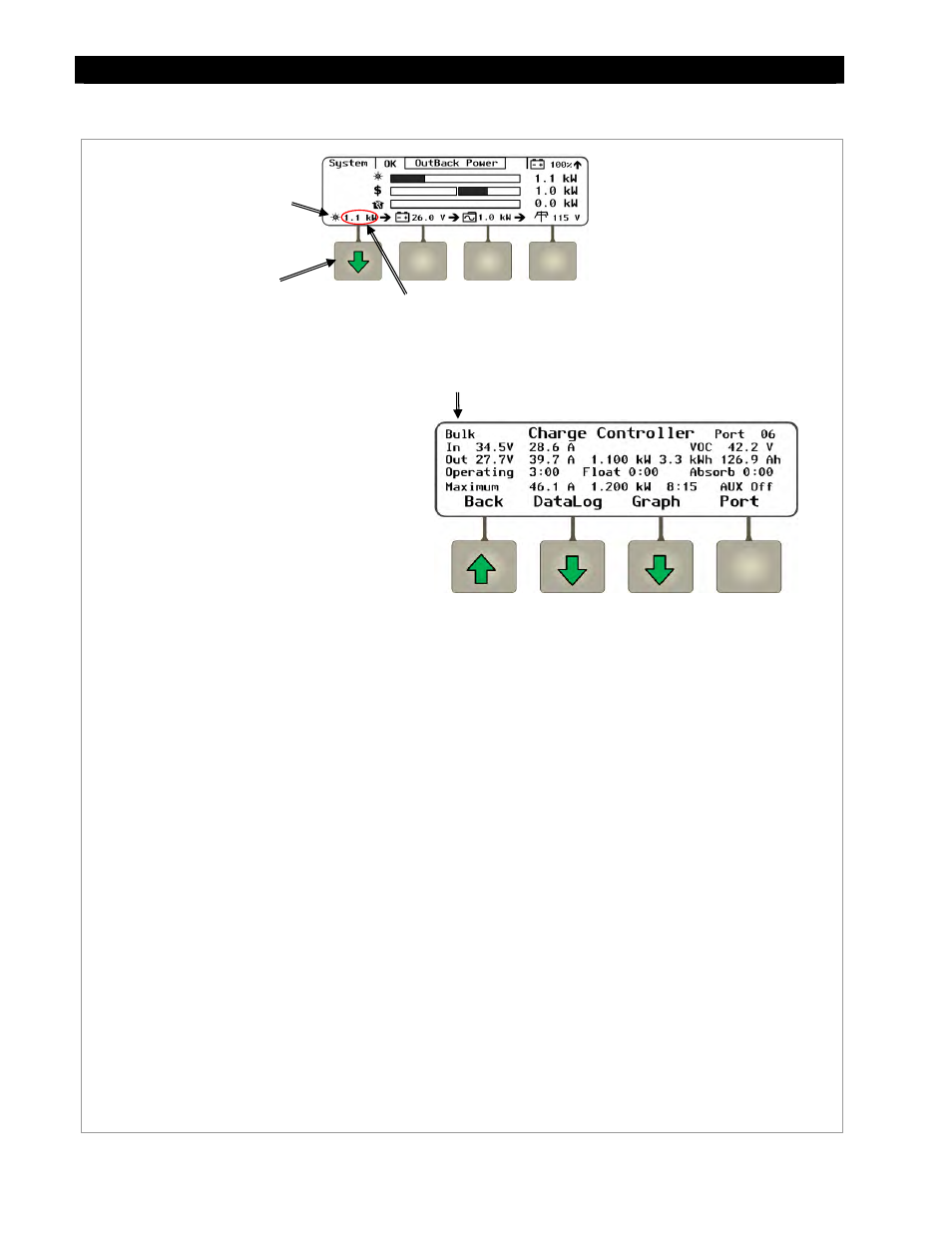
Charge Controller Soft Key
Figure 48
Charge Controller Soft Key Screens
Charge Controller Soft Key
Press this soft key to view FLEXmax
charge controller status information.
If no charge controller is present,
the PV icon will be blank and this
soft key will be inoperative.
Charge Controller Modes:
Bulk
Absorb
Float
EQ
Silent
See the charge controller
Owner’s Manual for
descriptions of each mode.
Soft Keys:
controller statistics that are maintained as a
continuous daily log. These screens are all
shown beginning on page 53.
plot various charge controller information
over time. The graphs include inverter and
charger wattage, power imported from an AC
source, battery voltage, and others. These
screens are all shown beginning on page 54.
connected to the network. If more than one
charge controller is installed in the system,
pressing the
through each controller.
Screen Items:
The upper left corner of the screen shows the FLEXmax charge
controller’s current mode of operation.
Bulk
is shown in this
illustration.
In displays the present PV array operating voltage and the
current being harvested from the array.
VOC displays the open-circuit voltage available from the PV.
Out displays the present battery voltage and the current
being delivered from the charge controller(s) to charge the
battery bank. To the right, this line displays the number of
kilowatt-hours and amp-hours accumulated that day.
Operating displays the total hours the charger has operated
that day in any stage.
Float displays the run time of the float timer when in
float stage.
Absorb displays the run time of the absorption timer when in
absorption stage.
Maximum displays the maximum amperage and wattage
harvested from the PV array that day, and the time both were
recorded.
The lower right corner shows the current status of the charge
controller’s Auxiliary (AUX) output. (See page 107.)
PV Icon
Charge Controller’s
Mode
The value displayed here switches between
kilowatt output and the daily kilowatt-hours produced.