Operation, Inverter, Figure 29 inverter battery screen – Outback Power Systems MATE3 Owners Manual User Manual
Page 43
Operation
900-0117-01-00 Rev C
41
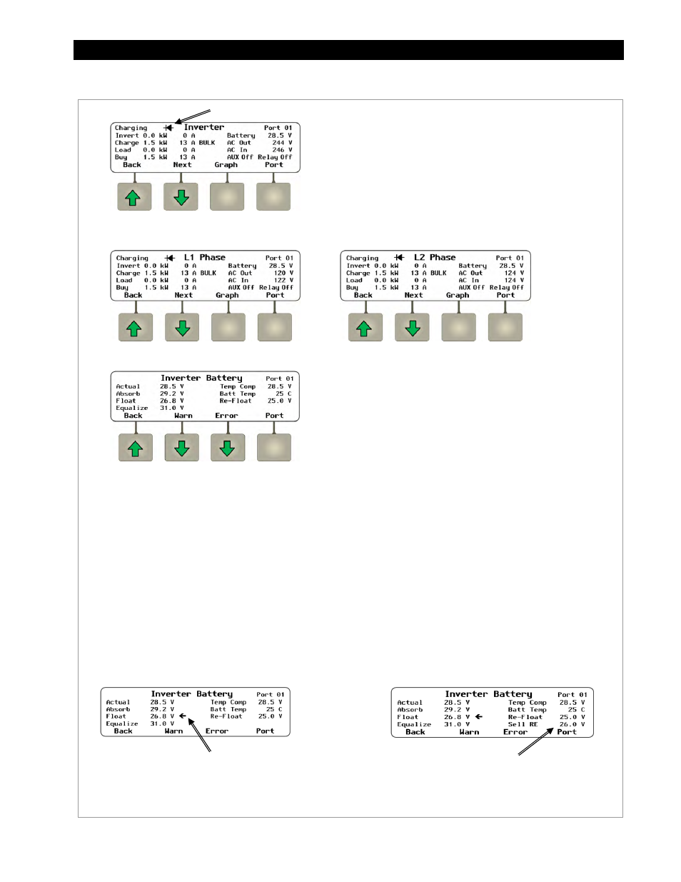
From the
Inverter
screen, the
Figure 29
Inverter Battery Screen
Soft Keys:
of non-critical inverter faults and other
information. These screens are shown
beginning on page 42.
inverter faults. These screens are shown
beginning on page 43.
to the network.
Screen Items:
Actual displays the uncompensated battery voltage.
Absorb displays the Absorption voltage setting which was
programmed into the inverter’s charger. During the bulk and
absorption stages, this is the target voltage used by the charger.
Float displays the Float voltage setting which was programmed
into the inverter’s charger. During the float stage, this is the
target voltage used by the charger.
Equalize displays the Equalization voltage setting which was
programmed into the inverter’s charger. During the equalization
charging cycle, this is the target voltage used by the charger.
Temp Comp displays the corrected battery voltage after
temperature readings are taken into account from the Remote
Temperature Sensor (RTS). If no RTS is present,
Temp Comp and
Actual will read the same.
Batt Temp displays the battery temperature in degrees Celsius,
as measured by the RTS. This reading is only valid for port 1 on
the HUB. If other ports are selected, or if no RTS is present, the
characters ### will be displayed.
Re-Float displays the Re-Float setting which was programmed
into the inverter’s charger. This is the voltage used for the
inverter to return from Silent mode to the float stage.
Sell RE voltage is the target voltage for the inverter to switch to
Sell Mode. (Grid-interactive systems only)
NOTE: If an arrow appears next to the items
Absorb, Float, or
Equalize, it indicates the charger is in that stage. The arrow will
not appear if the charger is in the bulk stage or Silent mode.
NOTE: In grid-interactive systems, the
Sell RE voltage will be included.
NOTE: The
L1 Phase and L2 Phase screens are only present in
the Radian class. The screen items are the same as those listed
on page 40, but the AC voltage readings are those of the
individual L1 and L2 phases. These screens are not present in
FX-class inverters. The next screen is
Inverter Battery.
In any of these screens, a diode symbol may appear to the left of
the screen name to indicate “diode charging” mode. This is a
low-power mode that allows fine control of charging, selling,
and load support. (See the Operator’s Manual for information.)
L1 Phase Screen (Radian only)
L2 Phase Screen (Radian only)
Diode Charging