3 commissioning examples, 3 kty84-130 connection, Commissioning examples – NORD Drivesystems BU0180 User Manual
Page 68
SK 180E Manual for frequency inverters
68
Pre-series version
BU 0180 GB-0914
5.2.3
Commissioning examples
All devices can be operated in the condition in which they are delivered. The standard motor data of a
4-pole IE1 standard asynchronous motor of the same power are parameterised. The PTC input must be
bypassed, if a motor with PTC is not available. Parameter (P428) must be changed if an automatic start-up
with "Mains On" is required.
5.2.3.1
Minimal configuration
The frequency inverter provides all the necessary low voltages (24V DC / 10V DC).
Function
Setting
Setpoint
External 10 kOhm potentiometer
Controller enable
External switch S1
Minimal configuration with options
In order to implement completely autonomous operation (i.e. independent of control cables etc.) a
potentiometer unit (SK CU4-POT) is required. In this way, the required speed and direction control can be
achieved with only a single mains cable (single phase or three-phase, according to the version) (see
connection example in Section 3.3.1).
5.3 KTY84-130 connection
The current vector control of the SK 1x0E series can be further optimised by the use of a KTY84-130
temperature sensor (R
th(0°C)
=500
, R
th(100°C)
=1000
). By continuous measurement of the motor temperature,
the highest precision of regulation by the frequency inverter and the associated optimum speed precision of
the motor is achieved at all times. As the temperature measurement starts immediately after the (mains)
switch-on of the frequency inverter, the frequency inverter provides immediate optimum control, even if the
motor has a considerably increased temperature after an intermediate "Mains off / Mains on" of the
frequency inverter.
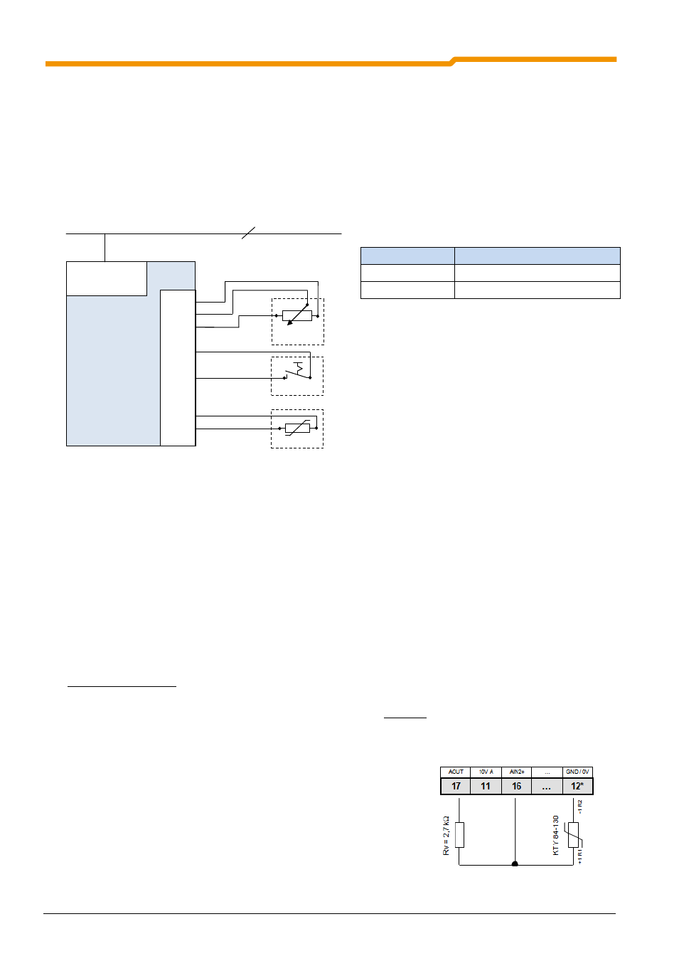
Connection examples:
SK 1x0E
Connection of a KTY-84 to either of the two analog inputs of the SK 1x0E is possible. In the following examples,
analog input 2 of the frequency inverter is used.
1. The motor data P201-P207 must be set according to the rating plate.
2. The motor stator resistance P208 is determined at 20°C with P220 = 1.
3. Function analog input 2, P400 [-02] = 30 (Motor temperature)
4. The mode analog input 2 P401 [-06] = 1 (negative temperatures are
also measured)
Adjustment of analog input 2: P402 [-06] = 1.54V and
P403 [-06] = 2.64V (with R
V
= 2.7 kOhm)
5. Adjust time constants: P404 [-02] = 400ms
(Filter time constant is maximum)
6. Motor temperature control (display): P739 [-03]
* If necessary, also Terminal 40
Frequency inverter
SK 1x0E-...
Co
ntro
l terminal b
ar
12/40
14
11
.
43
.
21
22
.
38
39
L1 - L2/N - L3
230/400 V
1/3~ 230/400V + PE
Switch S1
Motor PTC
Potentiometer
10kOhm