1 mounting the housing box – NORD Drivesystems BU0180 User Manual
Page 19
2 Assembly and installation
BU 0180 GB-0914
Pre-series version
19
2.1.1
Mounting the housing box
On delivery of a complete drive unit (gear unit + motor + frequency inverter) the frequency inverter is always
fully installed and tested.
NOTE
Installation of an IP66-compliant frequency inverter must be carried out by NORD, as special
measures have to be implemented. IP66 components retrofitted on site cannot ensure that this
protection class is guaranteed.
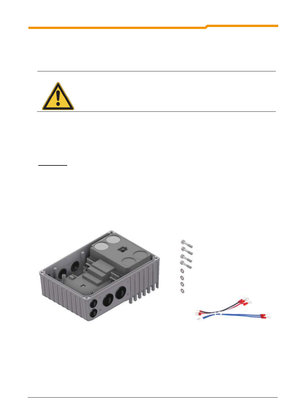
When delivered separately, the frequency inverter includes the following components:
Frequency inverters
Screws and contact washers for mounting the motor terminal box.
Pre-fabricated cable for motor and PTC connections
Procedures:
1.
If necessary, remove the original terminal box from the NORD motor, so that only the base of the termi-
nal box and the terminal strip remain.
2.
Set the jumpers for the correct motor circuit and connect the pre-fabricated cables for motor and PTC
connections to the respective connection points on the motor.
3.
Mount the cast housing on the terminal box base of the NORD motor using the existing screws and seal
as well as the enclosed lock washers. Position the cast housing with the cooling fins towards the fan end
of the motor. Check the adaptability for different motor manufacturers.
4.
Connect the motor cables U, V, W to the power terminal block and the PTC cable TF+, TF- to the control
terminal block 38, 39.